
Instruction Manual


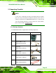
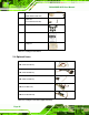
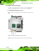

Table Of Contents
- 1 Introduction
- 2 Unpacking
- 3 Connectors
- 3.1 Peripheral Interface Connectors
- 3.2 Internal Peripheral Connectors
- 3.2.1 12V / 5V Power Connector
- 3.2.2 ATX Power Supply Enable Connector
- 3.2.3 Audio Kit Connector
- 3.2.4 Battery Connector
- 3.2.5 CompactFlash® Connector
- 3.2.6 Fan Connector
- 3.2.7 Digital I/O Connector
- 3.2.8 Keyboard/Mouse Connector
- 3.2.9 LAN Connector
- 3.2.10 LCD Inverter Connector
- 3.2.11 LED and +5V Output Connector
- 3.2.12 PCI-104 Connector
- 3.2.13 Power Button Connector
- 3.2.14 Reset Button Connector
- 3.2.15 RS-232 Serial Port Connectors
- 3.2.16 RS-422/485 Serial Port Connector
- 3.2.17 LVDS LCD Connector
- 3.2.18 SATA Drive Connector
- 3.2.19 SPI Flash Connector
- 3.2.20 USB Connector
- 3.2.21 VGA Connector
- 4 Installation
- 5 BIOS
- A BIOS Options
- B Terminology
- C Watchdog Timer
- D Hazardous Materials Disclosure

PM-945GSE-N270 User Manual
Page 25
2.3 Unpacking Checklist
NOTE:
If some of the components listed in the checklist below are missing,
please do not proceed with the installation. Contact the IEI reseller or
vendor you purchased the PM-945GSE-N270 from or contact an IEI
sales representative directly. To contact an IEI sales representative,
please send an email to sales@iei.com.tw
.
2.3.1 Package Contents
The PM-945GSE-N270 is shipped with the following components:
Quantity Item and Part Number Image
1 PM-945GSE-N270-R10
1 Keyboard/Mouse cable
(P/N:32000-023800-RS)
1 LAN cable
(P/N: 32000-055702-RS)
1 Power cable
(P/N: 32000-130300-RS)
1 Quad port RS-232 cable
(P/N: 32200-147900-RS)
1 SATA cable
(P/N:
32000-062800-RS)