
Instruction Manual


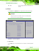


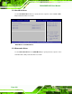
Table Of Contents
- 1 Introduction
- 2 Unpacking
- 3 Connectors
- 3.1 Peripheral Interface Connectors
- 3.2 Internal Peripheral Connectors
- 3.2.1 12V / 5V Power Connector
- 3.2.2 ATX Power Supply Enable Connector
- 3.2.3 Audio Kit Connector
- 3.2.4 Battery Connector
- 3.2.5 CompactFlash® Connector
- 3.2.6 Fan Connector
- 3.2.7 Digital I/O Connector
- 3.2.8 Keyboard/Mouse Connector
- 3.2.9 LAN Connector
- 3.2.10 LCD Inverter Connector
- 3.2.11 LED and +5V Output Connector
- 3.2.12 PCI-104 Connector
- 3.2.13 Power Button Connector
- 3.2.14 Reset Button Connector
- 3.2.15 RS-232 Serial Port Connectors
- 3.2.16 RS-422/485 Serial Port Connector
- 3.2.17 LVDS LCD Connector
- 3.2.18 SATA Drive Connector
- 3.2.19 SPI Flash Connector
- 3.2.20 USB Connector
- 3.2.21 VGA Connector
- 4 Installation
- 5 BIOS
- A BIOS Options
- B Terminology
- C Watchdog Timer
- D Hazardous Materials Disclosure

PM-945GSE-N270 User Manual
Page 100
5.5.3 Hard Disk Drives
Use the Hard Disk Drives menu to specify the boot sequence of the available HDDs.
Only installed hard drives are shown.
BIOS SETUP UTILITY
Main Advanced PCIPNP Boot Security Chipset Exit
Hard Disk Drives
> 1st Drive [Hard Drive 1]
> 2nd Drive [Hard Drive 2]
> 3rd Drive [Hard Drive 3]
Specifies the boot
sequence from the
available devices.
Select Screen
Select Item
Enter Go to SubScreen
F1 General Help
F10 Save and Exit
ESC Exit
v02.61 ©Copyright 1985-2006, American Megatrends, Inc.
BIOS Menu 15: Hard Disk Drives
5.5.4 Removable Drives
Use the Removable Drives menu (BIOS Menu 16) to specify the boot sequence of the
removable drives. Only connected drives are shown.