
Instruction Manual


PCISA-945GSE CPU Card
Page 56
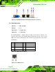
Figure 4-22: TV Connector Pinout Locations
PIN NO. DESCRIPTION PIN NO. DESCRIPTION
S-Video Connector
1 GND 2 AGREEN_Y
3 GND 4 ARED_C
RCA Connector (only video signal)
5 GND 6 ABLUE_CVBS
Table 4-22: TV Port Connector Pinouts
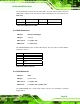
4.2.21 USB Connectors
CN Label: USB01, USB23
CN Type:
8-pin header (2x4)
CN Location:
See
8Figure 4-23
CN Pinouts:
See
8Table 4-23
The 2x4 USB pin connectors provide connectivity to four USB 1.1 or USB 2.0 devices.
Each USB connector can support two USB devices. Additional external USB ports are
found on the rear panel. The USB ports are used for I/O bus expansion.