
Instruction Manual


PCISA-945GSE CPU Card
Page 49
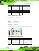
CN Type:
30-pin crimp (2x15)
CN Location:
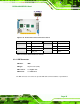
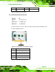
See
Figure 4-16
CN Pinouts:
See
Table 4-16
The 30-pin LVDS LCD connector can be connected to single channel or dual channel,
18-bit or 36-bit LVDS panel.
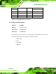
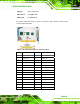
Figure 4-16: LVDS LCD Connector Pinout Locations
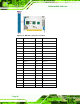
PIN NO. DESCRIPTION PIN NO. DESCRIPTION
1 GROUND 2 GROUND
3 LVDSA_Y0+ 4 LVDSA_Y0-
5 LVDSA_Y1+ 6 LVDSA_Y1-
7 LVDSA_Y2+ 8 LVDSA_Y2-
9 LVDSA_CLK+ 10 LVDSA_CLK-
11 NC 12 NC
13 GROUND 14 GROUND
15 LVDSB_Y0+ 16 LVDSB_Y0-
17 LVDSB_Y1+ 18 LVDSB_Y1-
19 LVDSB_Y2+ 20 LVDSB_Y2-
21 LVDSB_CLK+ 22 LVDSB_CLK-
23 NC 24 NC
25 GROUND 26 GROUND
27 VCC_LVDS 28 VCC_LVDS