
Instruction Manual


PCISA-945GSE CPU Card
Page 47
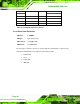
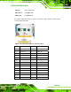
PIN NO. DESCRIPTION PIN NO. DESCRIPTION
39 HDD ACTIVE# 40 GROUND
Table 4-13: IDE Connector Pinouts
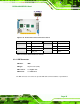
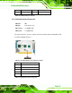
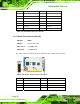
4.2.12 Infrared Interface Connector
CN Label: IR1
CN Type:
5-pin header (1x5)
CN Location:
See
7Figure 4-14
CN Pinouts:
See
7Table 4-14
The infrared interface connector supports both Serial Infrared (SIR) and Amplitude Shift
Key Infrared (ASKIR) interfaces.
Figure 4-14: Infrared Connector Pinout Locations
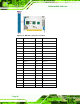
PIN NO. DESCRIPTION
1 VCC
2 NC
3 IR-RX
4 GND
5 IR-TX
Table 4-14: Infrared Connector Pinouts