
Instruction Manual


PCISA-945GSE CPU Card
Page 45
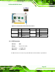
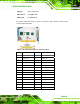
Figure 4-12: Front Panel Connector Pinout Locations
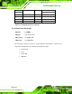
FUNCTION PIN DESCRIPTION FUNCTION PIN DESCRIPTION
Power button 1 PWR_BTN+ Power LED 2 PWR_LED+
3 PWR_BTN- 4 PWR_LED-
HDD LED 5 HDD_LED+ Reset button 6 RESET+
7 HDD_LED- 8 RESET-
Table 4-12: Front Panel Connector Pinouts
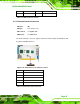
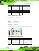
4.2.11 IDE Connector
CN Label: IDE1
CN Type:
40-pin header (2x20)
CN Location:
See
7Figure 4-13
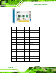
CN Pinouts:
See
7Table 4-13
The IDE connector can connect to up to two IDE devices like hard drives or optical drives.