
Owner's manual

PAC-1000G QIG IEI Technology Corp. Page 6
S
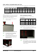
TEP 7.1: DRIVE BRACKET REMOVAL
To remove the drive bracket, please follow the steps below:
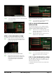
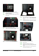
Step 1: Remove the four drive bracket retention screws from the
right side of the chassis.
Figure 14: Four Side Drive Bracket Retention Screws
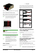
Step 2: Remove the one internal drive bracket retention screw
from the top of the fan bracket.
Figure 15: Internal Drive Bracket Retention Screw
S
TEP 7.2: INTERNAL HDD INSTALLATION
The PAC-1000G can support an HDD to be installed on the
right side of the drive bracket. To install a 3.5” HDD into the
right side of the drive bracket, please follow the steps below.
Step 1: Remove the drive bracket. To do this, please
refer to
STEP 8.1: DRIVE BRACKET REMOVAL.
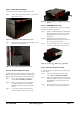
Step 2: Slide a 3.5” HDD into the 3.5” drive bay. Make
sure both the 4-pin power connector and the
IDE/SATA connecter are at the rear of the drive
bracket.
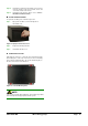
Step 3: To secure the 3.5” drive to the drive bracket,
insert four retention screws, two on each side.
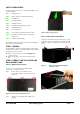
Step 0:
Figure 16: Secure an HDD to the Right Side of the Drive
Bracket
STEP 7.3: FDD/HDD INSTALLATION
To install a 3.5” FDD/HDD into the 3.5” front accessible drive
bracket, please follow the steps below:
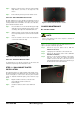
Step 1: Slide a 3.5” FDD/HDD into the 3.5” FDD drive bay.
Make sure both the 4-pin power connector and
the IDE/SATA connector are at the rear of the
drive bracket.
Step 2: Align the retention screw holes in the 3.5”
FDD/HDD drive with the retention screw holes in
the 3.5” front accessible drive bay.
Step 3: Insert four retention screws, two on each side to
secure the 3.5” FDD/HDD to the drive bracket.
Figure 17:
Secure a 3.5"FDD to the 3.5"Drive Bay
STEP 7.4: OPTICAL DRIVE INSTALLATION
To install a 5.25” drive into the drive bracket, please follow
the steps below.
Step 1: Remove the drive bracket. To do this, please
refer to S
TEP 8.1: DRIVE BRACKET REMOVAL.
Step 2: Slide a 5.25” optical drive into the 5.25” drive bay
making sure both the 4-pin power connector and
the IDE/SATA connector are at the rear of the
drive bracket.
Step 3: Insert four retention screws, two on each side of
the drive bay to secure the 5.25” optical drive.
Step 0: