
Manual


NOVA-945GSE 5.25” SBC
Page 36
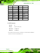
INV2_POWER
ENABKL_C
INV2
CON5/2mm
JST_1X5_2M
M
1
1
2
2
3
3
4
4
5
5
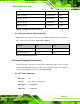
Figure 3-7: Panel Backlight Connector (2) Pinout Locations
PIN NO. DESCRIPTION
1 N/C
2 GROUND
3 +12V
4 GROUND
5 BACKLIGHT Enable
Table 3-7: Panel Backlight Connector (2) Pinouts
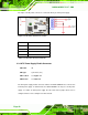
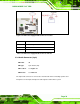
3.3.6 CompactFlash® Socket
CN Label: J9 (solder side)
CN Type:
50-pin header (2x25)
CN Location: See
Figure 3-8
CN Pinouts: See
Table 3-8
A CF Type II memory card is inserted to the CF socket on the solder side of the
NOVA-945GSE.