
Manual


NANO-PV-D4252/N4552/D5252 EPIC SBC
Page 21
CN Type:
8-pin header (2x4)
CN Location:
See Figure 3-8
CN Pinou
ts:
See Table 3-9
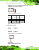
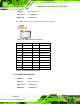
The front pa
nel connector connects to external switches and indicators to monitor and
controls the motherboard. These indicators and switches include:
Power button
Reset
Power LED
HDD LED
Figure 3-8: Front Panel Connector Location
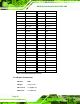
FUNCTION PIN DESCRIPTION FUNCTION PIN DESCRIPTION
1 PWR_BTN+ 2 PWR LED Power Button
3 GND
Power LED
4 GND
5 SATA LED PWT 6 RESET SATA LED
7 SATA_LED#
Reset
8 GND
Table 3-9: Front Panel Connector Pinouts
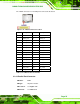
3.2.8 Keyboard/Mouse Connector
CN Label: KB/MS1
CN Type:
6-pin wafer (1x6)
CN Location:
See Figure 3-9
CN Pinou
ts:
See Table 3-10