
Owner's manual


NANO-945GSE EPIC Motherboard
Page 42
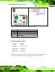
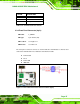
Figure 3-6: Audio Connector Location (9-pin)
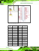
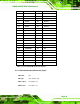
PIN NO. DESCRIPTION PIN NO. DESCRIPTION
1 SYNC 2 BITCLK
3 SDOUT 4 PCBEEP
5 SDIN 6 RST#
7 VCC 8 GND
9 +12V
Table 3-6: Audio Connector Pinouts (9-pin)
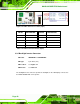
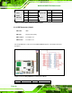
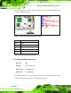
3.3.5 Backlight Inverter Connector
CN Label: INVERTER1 and INVERTER2
CN Type:
5-pin wafer (1x5)
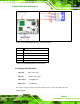
CN Location: See Figure 3-7
CN Pinou
ts: See Table 3-7
The ba
cklight inverter connectors provide the backlights on the LCD display connected to
the NANO-945GSE with +12V of power.