
User Manual


LCD-KIT
Page 26
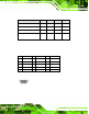
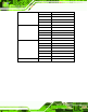
Pin Description Pin Description Pin Description
1 TMDS Data2- 9 TMDS Data1- 17 TMDS Data0-
2 TMDS Data2+ 10 TMDS Data1+ 18 TMDSData0+
3 TMDS Data2/4 Shield 11 TMDS Data1/3 Shield 19 TMDS Data0/5 Shield
4 TMDS Data4- 12 TMDS Data3- 20 TMDS Data5-
5 TMDS Data4+ 13 TMDS Data3+ 21 TMDS Data5+
6 DDC Clock [SCL] 14 +5 V Power 22 TMDS Clock Shield
7 DDC Data [SDA] 15 G r ound (for +5 V) 23 TMDS Clock +
8 Analog vertical sync 16 Hot Plug Detect 24 TMDS Cloc k -
Table 5-3: DVI-D Connector Pinouts
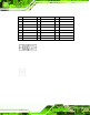
Figure 5-2: DVI-D Connector
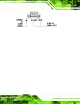
5.4.3 12V Power Connector
Use the rear pan el +12 V DC ( or 9~36 V DC on M models) jack to connect the monitor to a
power source.
Figure 5-3: 12V Po wer Connector
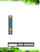
5.4.4 Optional Te rm in a l Blo ck
Use the rear panel 3-pin terminal block DC power connector to connect the m onitor to a
DC power source.