
User guide
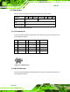
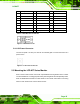

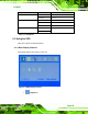
Table Of Contents
- 1 Introduction
- 2 Mechanical Overview
- 3 LCD Specifications
- 3.1 LCD Specifications
- 3.1.1 LCD Overview
- 3.1.2 LCD-KIT190G LCD Specifications
- 3.1.3 LCD-KIT170G LCD Specifications
- 3.1.4 LCD-KIT150G LCD Specifications
- 3.1.5 LCD-KIT121GX LCD Specifications
- 3.1.6 LCD-KIT121G LCD Specifications
- 3.1.7 LCD-KIT104GH LCD Specifications
- 3.1.8 LCD-KIT84GH LCD Specifications
- 3.1.9 LCD-KIT65GH LCD Specifications
- 3.2 Power Adapters
- 3.1 LCD Specifications
- 4 AD Boards
- 5 Installation
- 6 OSD Controls
- A Certifications
- B Safety Precautions
- C smartOSD
LCD-KIT
Page 45
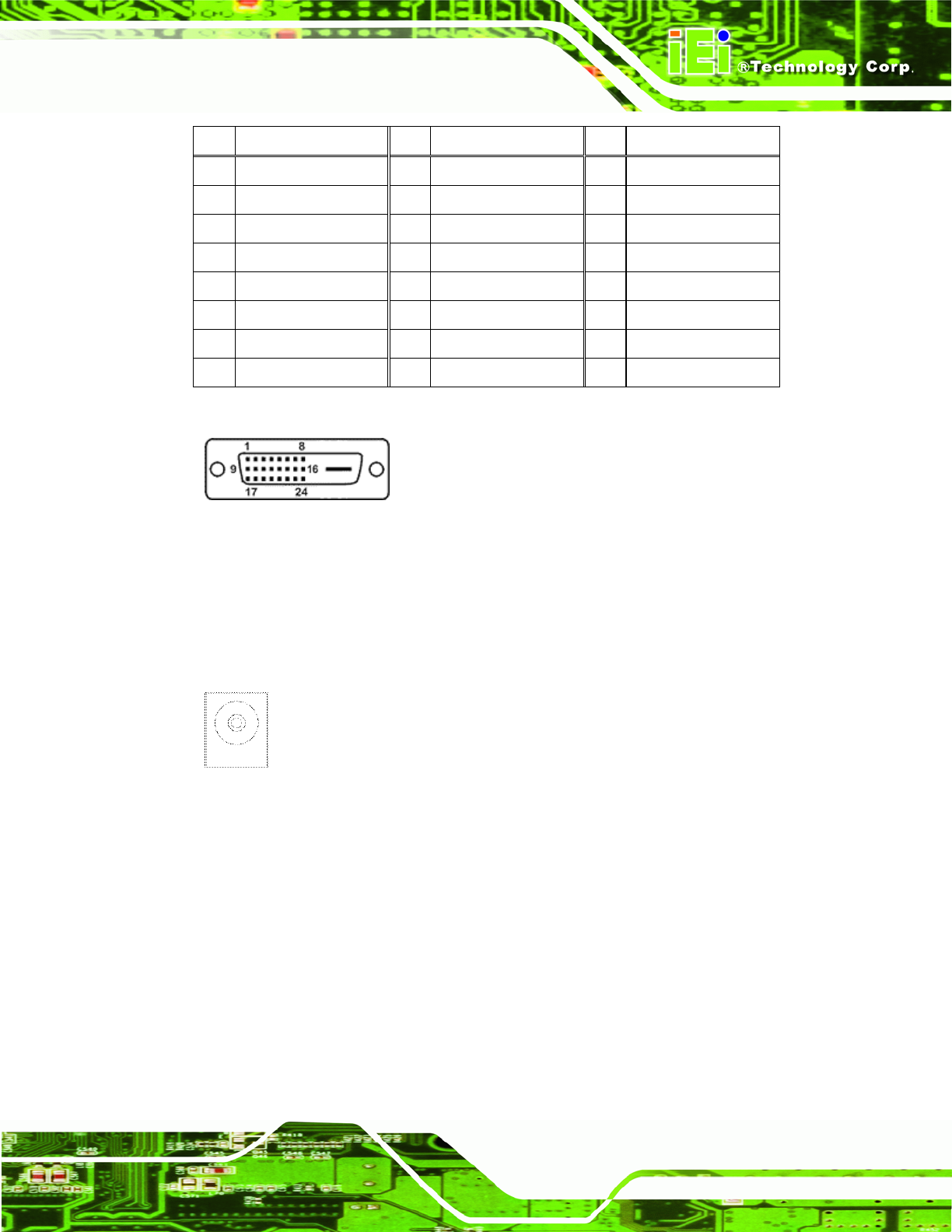
Pin Description Pin
Description Pin
Description
1 TMDS Data2- 9 TMDS Data1- 17 TMDS Data0-
2 TMDS Data2+ 10 TMDS Data1+ 18 TMDSData0+
3 TMDS Data2/4 Shield 11 TMDS Data1/3 Shield
19 TMDS Data0/5 Shield
4 TMDS Data4- 12 TMDS Data3- 20 TMDS Data5-
5 TMDS Data4+ 13 TMDS Data3+ 21 TMDS Data5+
6 DDC Clock [SCL] 14 +5 V Power 22 TMDS Clock Shield
7 DDC Data [SDA] 15 Ground (for +5 V) 23 TMDS Clock +
8 Analog vertical sync 16 Hot Plug Detect 24 TMDS Clock -
Table 5-3: DVI-D Connector Pinouts
Figure 5-2: DVI-D Connector
5.4.3 12V Power Connector
Use the rear panel +12V DC (or 9~36V DC on M models) jack to connect the monitor to a
power source.
Figure 5-3: 12V Power Connector
5.5 Mounting the LCD-KIT Series Monitor
Each LCD-KIT series monitor comes with a preinstalled mounting bracket with a number
of holes available for mounting purposes that system integrators will find especially useful.
Refer to Sections
2.4 and 2.5 for further details on the number and location of mounting
holes for each model of the LCD-KIT series monitor.