
User guide
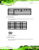
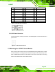

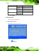
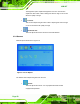
Table Of Contents
- 1 Introduction
- 2 Mechanical Overview
- 3 LCD Specifications
- 3.1 LCD Specifications
- 3.1.1 LCD Overview
- 3.1.2 LCD-KIT190G LCD Specifications
- 3.1.3 LCD-KIT170G LCD Specifications
- 3.1.4 LCD-KIT150G LCD Specifications
- 3.1.5 LCD-KIT121GX LCD Specifications
- 3.1.6 LCD-KIT121G LCD Specifications
- 3.1.7 LCD-KIT104GH LCD Specifications
- 3.1.8 LCD-KIT84GH LCD Specifications
- 3.1.9 LCD-KIT65GH LCD Specifications
- 3.2 Power Adapters
- 3.1 LCD Specifications
- 4 AD Boards
- 5 Installation
- 6 OSD Controls
- A Certifications
- B Safety Precautions
- C smartOSD
LCD-KIT
Page 44
5.4 Connectors
Table 5-1 lists the rear panel connectors for the LCD-KIT series monitors.
LCD-KIT 65GH 84GH 104GH 121G/GX 150G 170G 190G
DVI-D - Yes
VGA Yes
Power (12V Jack) Yes
Table 5-1: Rear Panel Connectors
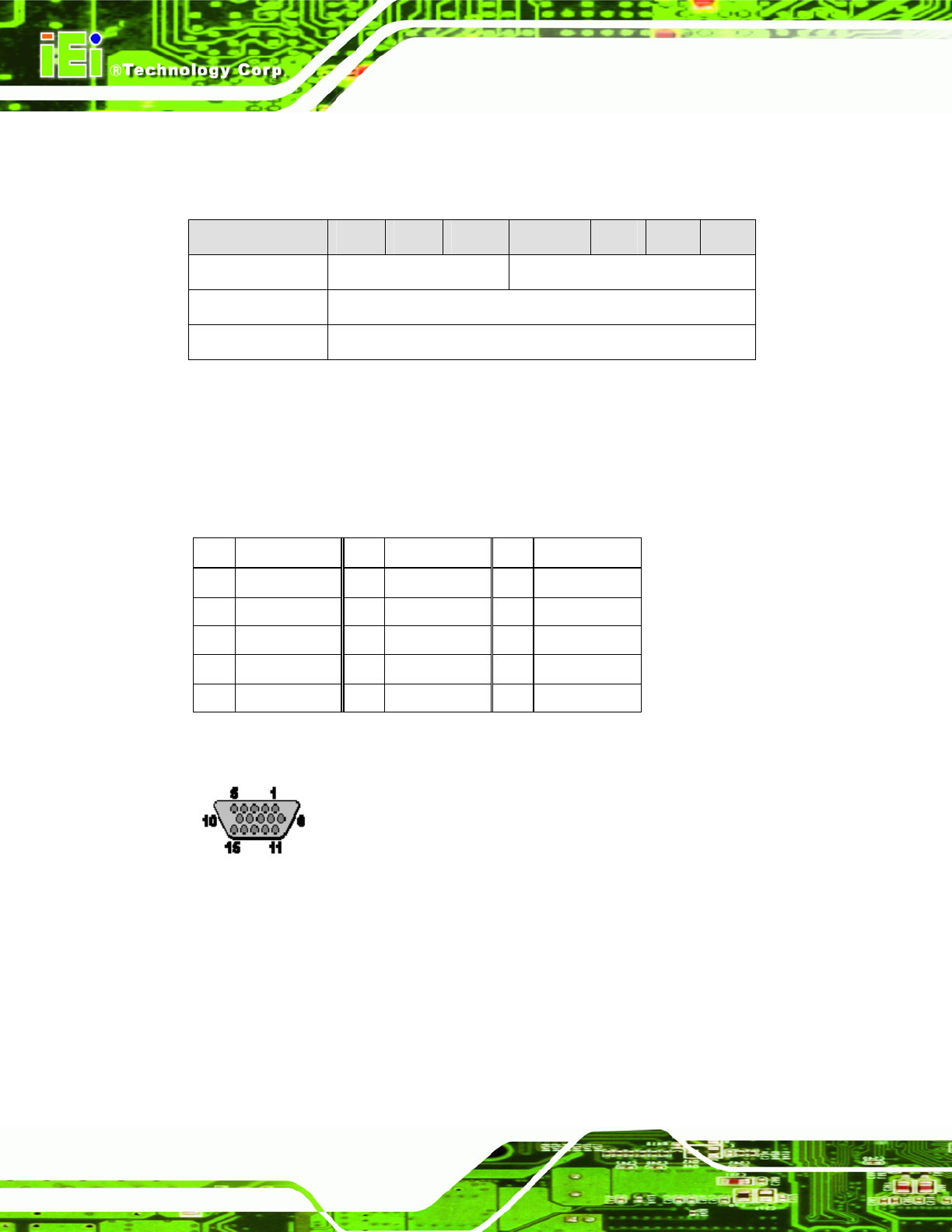
5.4.1 VGA Connector
Use the rear panel standard 15-pin female VGA connector to connect the monitor to the
system graphics interface.
Pin Description Pin Description Pin
Description
1 RED 6 GROUND 11 NC
2 GREEN 7 GROUND 12 DDCDAT
3 BLUE 8 GROUND 13 HSYNC
4 NC 9 NC 14 VSYNC
5 GROUND 10 GROUND 15 DDCCLK
Table 5-2: VGA Connector Pinouts
Figure 5-1: VGA Connector
5.4.2 DVI-D Connector
Use the rear panel standard 24-pin female DVI-D connector to connect the monitor to the
system graphics interface.