
User guide
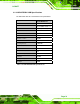
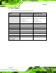
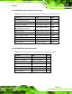
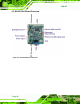
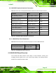
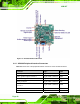
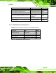
Table Of Contents
- 1 Introduction
- 2 Mechanical Overview
- 3 LCD Specifications
- 3.1 LCD Specifications
- 3.1.1 LCD Overview
- 3.1.2 LCD-KIT190G LCD Specifications
- 3.1.3 LCD-KIT170G LCD Specifications
- 3.1.4 LCD-KIT150G LCD Specifications
- 3.1.5 LCD-KIT121GX LCD Specifications
- 3.1.6 LCD-KIT121G LCD Specifications
- 3.1.7 LCD-KIT104GH LCD Specifications
- 3.1.8 LCD-KIT84GH LCD Specifications
- 3.1.9 LCD-KIT65GH LCD Specifications
- 3.2 Power Adapters
- 3.1 LCD Specifications
- 4 AD Boards
- 5 Installation
- 6 OSD Controls
- A Certifications
- B Safety Precautions
- C smartOSD
LCD-KIT
Page 35
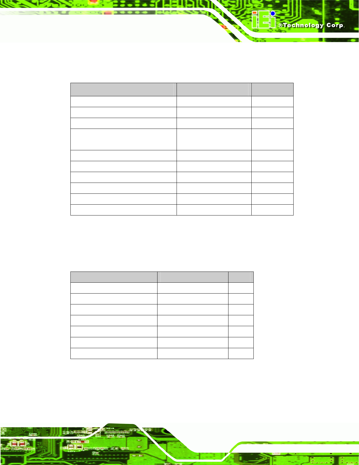
4.2.1 AV-9650 Peripheral Interface Connectors
Table 4-1 shows a list of the peripheral interface connectors on the AV-9650 AD board.
Connector Type Label
Auto-dimming connector 6-pin wafer connector CN7
Backlight Inverter connector 4-pin wafer connector CN16
Debug port connector 4-pin wafer connector CN9
External OSD and
LED indication connector
9-pin wafer connector CN10
LVDS connector 30-pin crimp connector CN15
Power input connector 3-pin connector CN2
Power output connector 2-pin wafer connector CN4
USB signal input connector 4-pin wafer connector CN17
Touchscreen connector 9-pin wafer connector J4
VGA connector 10-pin box header CN14
Table 4-1: AV-9650 Peripheral Interface Connectors
4.2.2 AV-9650 Rear Panel Connectors
Table 4-2 lists the rear panel connectors and buttons on the AV-9650 AD board.
Connector Type Label
DC 12V power connector DC Power Jack CN13
Serial port connector RS-232 connector J7
OSD function button Pushbutton S1
OSD function button Pushbutton S2
OSD function button Pushbutton S3
OSD function button Pushbutton S4
VGA connector 15-pin VGA connector VGA1
Table 4-2: AV-9650 Rear Panel Connectors