
User guide
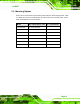
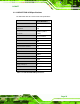

Table Of Contents
- 1 Introduction
- 2 Mechanical Overview
- 3 LCD Specifications
- 3.1 LCD Specifications
- 3.1.1 LCD Overview
- 3.1.2 LCD-KIT190G LCD Specifications
- 3.1.3 LCD-KIT170G LCD Specifications
- 3.1.4 LCD-KIT150G LCD Specifications
- 3.1.5 LCD-KIT121GX LCD Specifications
- 3.1.6 LCD-KIT121G LCD Specifications
- 3.1.7 LCD-KIT104GH LCD Specifications
- 3.1.8 LCD-KIT84GH LCD Specifications
- 3.1.9 LCD-KIT65GH LCD Specifications
- 3.2 Power Adapters
- 3.1 LCD Specifications
- 4 AD Boards
- 5 Installation
- 6 OSD Controls
- A Certifications
- B Safety Precautions
- C smartOSD
LCD-KIT
Page 21
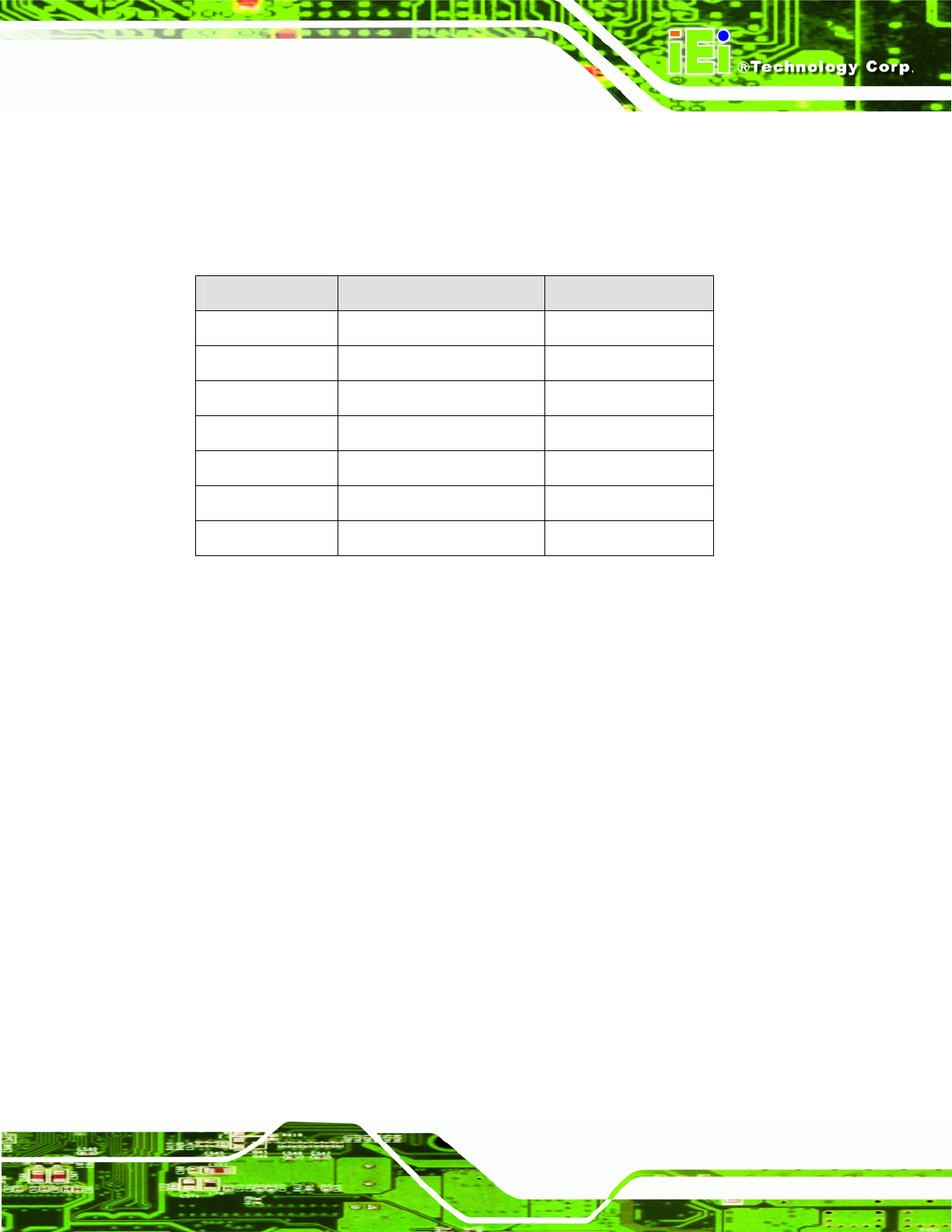
2.5 Mounting Options
Each LCD-KIT series monitor has mounting holes located on the mounting bracket. Table
2-3 details the number of mounting holes for each model of the LCD-KIT series monitor.
Refer to Section
2.4 for more information.
Model No. of Round Holes - Size No. of Slotted Holes
LCD-KIT190G 6 – 4 mm diameter 8
LCD-KIT170G 6 – 4.5 mm diameter 8
LCD-KIT150G 6 – 4.5 mm diameter 8
LCD-KIT121G/GX 4 – 3.5 mm diameter -
LCD-KIT104GH 4 – 3.5 mm diameter -
LCD-KIT84GH 4 – 3.5 mm diameter 4
LCD-KIT65GH 4 – 3.5 mm diameter 4
Table 2-3: Mounting Holes