
User guide

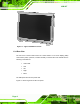
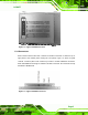
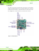
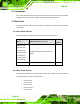
Table Of Contents
- 1 Introduction
- 2 Mechanical Overview
- 3 LCD Specifications
- 3.1 LCD Specifications
- 3.1.1 LCD Overview
- 3.1.2 LCD-KIT190G LCD Specifications
- 3.1.3 LCD-KIT170G LCD Specifications
- 3.1.4 LCD-KIT150G LCD Specifications
- 3.1.5 LCD-KIT121GX LCD Specifications
- 3.1.6 LCD-KIT121G LCD Specifications
- 3.1.7 LCD-KIT104GH LCD Specifications
- 3.1.8 LCD-KIT84GH LCD Specifications
- 3.1.9 LCD-KIT65GH LCD Specifications
- 3.2 Power Adapters
- 3.1 LCD Specifications
- 4 AD Boards
- 5 Installation
- 6 OSD Controls
- A Certifications
- B Safety Precautions
- C smartOSD
LCD-KIT
Page 5
Figure 1-2: Typical LCD-KIT Rear View
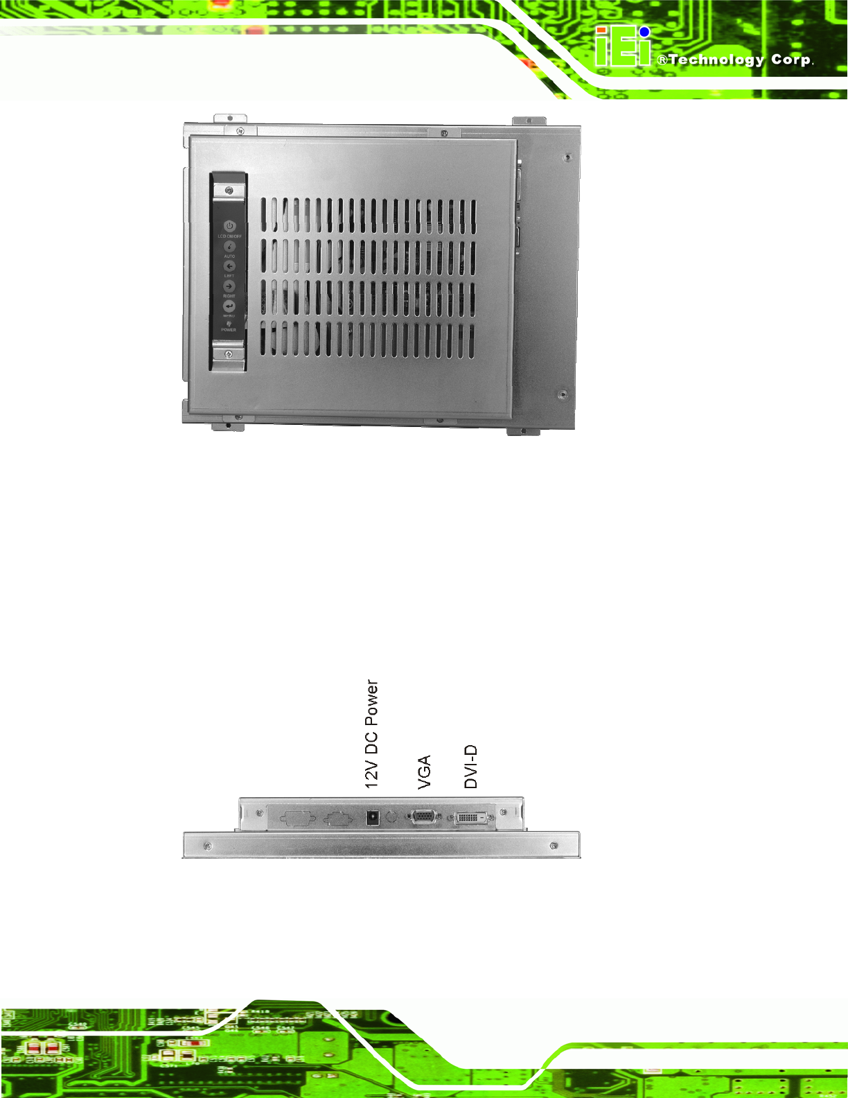
1.3.3 Connectors
Each LCD-KIT series monitor has a number of interface connectors on either the top or
right panel of the chassis (when viewing the rear panel).
Figure 1-3 shows a typical
LCD-KIT connector panel. Each model may include or exclude additional connectors.
Refer to Section
2.3 for listings of LCD-KITs and their connectors. All connectors are fully
described in Section
5.4.
Figure 1-3: Typical LCD-KIT Connectors