
Manual


KINO-PVN-D5251/D4251/ Mini ITX SBC
Page 33
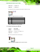
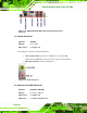
The KINO-PVN-D5251/D4251 is equipped with two built-in RJ-45 Ethernet controllers.
The controllers can connect to the LAN through the RJ-45 LAN connectors.
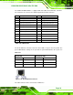
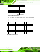
Pin Description Pin Description
P1 3.3V supply P2 LAN signal differential pair (0+)
P3 LAN signal differential pair (0-) P4 LAN signal differential pair (1+)
P5 LAN signal differential pair (1-) P6 LAN signal differential pair (2+)
P7 LAN signal differential pair (2-) P8 LAN signal differential pair (3+)
P9 LAN signal differential pair (3-) P10 GND
P11 Right LED signal(-) P12 Right LED signal(+)
P13 Left LED signal(-) P14 Left LED signal(+)
9 Chassis GND 10 Chassis GND
11 Chassis GND 12 Chassis GND
13 Chassis GND 14 Chassis GND
15 Chassis GND 16 Chassis GND
Table 3-20: LAN Pinouts
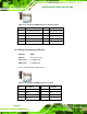
The RJ-45 Ethernet connectors have two status LEDs, one green and one yellow. The
green LED indicates activity on the port and the yellow LED indicates the speed. See
5Table 3-21.
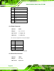
Speed LED Activity/Link LED
STATUS
DESCRIPTION STATUS DESCRIPTION
Off 10 Mbps connection Off No link
Green 100 Mbps connection Yellow Linked
Orange Gbps connection Blinking TX/RX activity 1
Table 3-21: RJ-45 Ethernet Connector LEDs
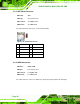
Figure 3-23: RJ-45 Ethernet Connector
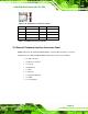
The USB connector can be connected to a USB device.