
Manual

KINO-PVN-D5251/D4251/ Mini ITX SBC
Page 21
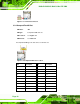
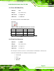
3.2.5 Flash SPI ROM (GT218)
CN Label: SPI2
CN Type:
6-pin header (2x4)
CN Location:
See Figure 3-7
CN Pinou
ts:
See Table 3-7
The co
nnector provides a GT218 BIOS update.
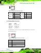
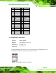
Figure 3-7: Flash SPI ROM (GT218) Connector Location
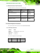
Pin Description Pin Description
1 GT218_SPI_VCC 2 ROM_2N_CS#
3 ROM_2N_SO 4 ROM_2N_SCLK
5 ROM_2N_SI 6 GND
Table 3-7: Flash SPI ROM (GT218) Connector Pinouts
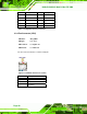
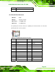
3.2.6 Front Panel Connector
CN Label: F_PANEL1
CN Type:
8-pin header (2x4)
CN Location:
See Figure 3-8
CN Pinou
ts:
See Table 3-8
The front pa
nel connector connects to external switches and indicators to monitor and
controls the motherboard. These indicators and switches include:
Power button
Reset
Power LED
HDD LED