
Owner manual


KINO-HM551
Page 21
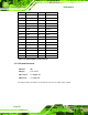
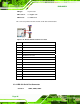
Figure 3-8: Infrared Connector Locations
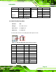
PIN NO. DESCRIPTION PIN NO.
DESCRIPTION
1 GND 2 +5V
3 Output 3 4 Output 2
5 Output 1 6 Output 0
7 Input 3 8 Input 2
9 Input 1 10 Input 0
Table 3-9: Infrared Connector Pinouts
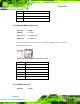
3.2.8 Inverter Connector
CN Label:
INVERTER1
CN Type:
5-pin wafer
CN Location:
See Figure 3-9
CN Pinou
ts:
See Table 3-10
The inverte
r connector provides power to an LCD panel.
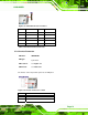
Figure 3-9: Inverter Connector Location
PIN NO. DESCRIPTION
1 BRIGHTNESS
2 GROUND