
Owner manual


KINO-HM551
Page 16
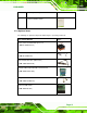
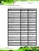
Figure 3-2: Audio Connector Location
PIN NO. DESCRIPTION PIN NO. DESCRIPTION
1 MIC-L 2 ANALOG GND
3 MIC-R 4 PRESENCE#
5 LINE-R 6 MIC-JD
7 FRONT-10 8 NC
9 LINE-L 10 INE-JD
Table 3-3: Audio Connector Pinouts
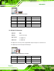
3.2.2 Digital I/O Connector
CN Label:
DIO1
CN Type:
10-pin header (2x5)
CN Location:
See Figure 3-3
CN Pinou
ts:
See Table 3-4
The digital I/O conn
ector provides programmable input and output for external devices.
The digital I/O provides 4-bit output and 4-bit input.
Figure 3-3: Digital I/O Connector Location
PIN NO. DESCRIPTION PIN NO. DESCRIPTION
1 GND 2 VCC
3 Output 3 4 Output 2
5 Output 1 6 Output 0