
Owner manual


KINO-GM45A Mini-ITX SBC
Page 19
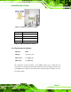
3.2.2 Backlight Inverter Connector
CN Label:
INVERTER1
CN Type:
5-pin wafer (1x5)
CN Location:
See
Figure 3-3
CN Pinouts:
See
Table 3-4
The backlight inverter connector provides the backlight on the LCD display connected to
the KINO-GM45A with +12V of power.
Figure 3-3: Panel Backlight Connector Pinout Locations
PIN NO. DESCRIPTION
1 LCD Backlight Control
2 GROUND
3 +12V
4 GROUND
5 Backlight Enable
Table 3-4: Panel Backlight Connector Pinouts
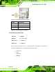
3.2.3 Digital I/O Connector
CN Label: DIO1
CN Type:
10-pin header (2x5)
CN Location:
See
Figure 3-4
CN Pinouts:
See
Table 3-5