
Manual
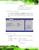
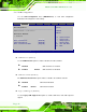

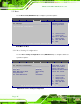

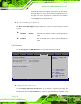
Table Of Contents
- Revision
- Copyright
- Table of Contents
- List of Figures
- List of Tables
- BIOS Menus
- 1 Introduction
- 2 Packing List
- 3 Connectors
- 3.1 Peripheral Interface Connectors
- 3.2 Internal Peripheral Connectors
- 3.2.1 Battery Connector
- 3.2.2 CPU Fan Connector
- 3.2.3 System Fan Connector
- 3.2.4 CPU Power Input Connector
- 3.2.5 Digital I/O Connector
- 3.2.6 Front Panel Connector
- 3.2.7 Memory Slot
- 3.2.8 Parallel Port Connector
- 3.2.9 Power Connector
- 3.2.10 RS-232 Serial Port Connector
- 3.2.11 RS-232/422/485 Serial Port Connector
- 3.2.12 SATA Drive Connectors
- 3.2.13 SMBus Connector
- 3.2.14 SPI Flash Connector
- 3.2.15 USB Connectors
- 3.2.16 VGA to LVDS Connector
- 3.3 External Peripheral Interface Connector Panel
- 4 Installation
- 5 BIOS
- A BIOS Options
- B Terminology
- C One Key Recovery
- D Watchdog Timer
- E Digital I/O Interface
- F Hazardous Materials Disclosure
KINO-G410 Mini-ITX Motherboard
Page 85
IRQ9
IRQ10
IRQ 11
IRQ 14
IRQ 15
DMA Channel# [Available]
Use the DMA Channel# option to assign a specific DMA channel to a particular PCI/PnP
device.
Available DEFAULT
The specified DMA is available to b
e used by
PCI/PnP devices
Reserved
The specified DMA is reserved for use by Legacy
ISA devices
Available DMA Channels are:
DM Channel 0
DM Channel 1
DM Channel 3
DM Channel 5
DM Channel 6
DM Channel 7
Reserved Memory Size [Dis abled]
Use the Reserved Memory Size BIOS option to specify the amount of memory that
should be reserved for legacy ISA devices.
Disabled DEFAULT
No memory block reserved for legacy ISA devices
16K
16KB reserved for legacy ISA devices
32K
32KB reserved for legacy ISA devices
64K
54KB reserved for legacy ISA devices