
Manual

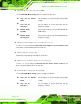
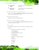

Table Of Contents
- Revision
- Copyright
- Table of Contents
- List of Figures
- List of Tables
- BIOS Menus
- 1 Introduction
- 2 Packing List
- 3 Connectors
- 3.1 Peripheral Interface Connectors
- 3.2 Internal Peripheral Connectors
- 3.2.1 Battery Connector
- 3.2.2 CPU Fan Connector
- 3.2.3 System Fan Connector
- 3.2.4 CPU Power Input Connector
- 3.2.5 Digital I/O Connector
- 3.2.6 Front Panel Connector
- 3.2.7 Memory Slot
- 3.2.8 Parallel Port Connector
- 3.2.9 Power Connector
- 3.2.10 RS-232 Serial Port Connector
- 3.2.11 RS-232/422/485 Serial Port Connector
- 3.2.12 SATA Drive Connectors
- 3.2.13 SMBus Connector
- 3.2.14 SPI Flash Connector
- 3.2.15 USB Connectors
- 3.2.16 VGA to LVDS Connector
- 3.3 External Peripheral Interface Connector Panel
- 4 Installation
- 5 BIOS
- A BIOS Options
- B Terminology
- C One Key Recovery
- D Watchdog Timer
- E Digital I/O Interface
- F Hazardous Materials Disclosure

KINO-G410 Mini-ITX Motherboard
Page 72
Normal D
EFAULT
The normal parallel port mode is the standard mode
for parallel port operation.
Bi-Directional
Parallel port outputs are 8-
bits long. Inputs are
accomplished by reading 4 of the 8 bits on the
status register.
ECP
The parallel port
operates in the extended
capabilities port (ECP) mode. The ECP mode
supports bi-directional communication between the
system and the parallel port device and the
transmission rates between the two are much faster
than the Normal mode
EPP
The parallel port operates in the enhanced parallel
port mode (EPP). The EPP mod
e supports
bi-directional communication between the system
and the parallel port device and the transmission
rates between the two are much faster than the
Normal mode.
ECP&EPP
The parallel port
operates in the extended
capabiliti
es port (ECP) mode. The ECP mode
supports bi-directional communication between the
system and the parallel port device and the
transmission rates between the two are much faster
than the Normal mode
The parallel port is also be compatible with EPP
devices described above
Parallel Port IRQ [IRQ7]
Use the Parallel Port IRQ selection to set the parallel port interrupt address.
IRQ5
IRQ5 is assigned as the parallel port interrupt address
IRQ7 D
EFAULT
IRQ7 is assigned as the parallel port interrupt address