
Manual
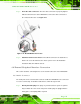
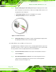
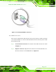
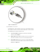

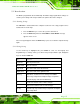
Table Of Contents
- Revision
- Copyright
- Table of Contents
- List of Figures
- List of Tables
- BIOS Menus
- 1 Introduction
- 2 Packing List
- 3 Connectors
- 3.1 Peripheral Interface Connectors
- 3.2 Internal Peripheral Connectors
- 3.2.1 Battery Connector
- 3.2.2 CPU Fan Connector
- 3.2.3 System Fan Connector
- 3.2.4 CPU Power Input Connector
- 3.2.5 Digital I/O Connector
- 3.2.6 Front Panel Connector
- 3.2.7 Memory Slot
- 3.2.8 Parallel Port Connector
- 3.2.9 Power Connector
- 3.2.10 RS-232 Serial Port Connector
- 3.2.11 RS-232/422/485 Serial Port Connector
- 3.2.12 SATA Drive Connectors
- 3.2.13 SMBus Connector
- 3.2.14 SPI Flash Connector
- 3.2.15 USB Connectors
- 3.2.16 VGA to LVDS Connector
- 3.3 External Peripheral Interface Connector Panel
- 4 Installation
- 5 BIOS
- A BIOS Options
- B Terminology
- C One Key Recovery
- D Watchdog Timer
- E Digital I/O Interface
- F Hazardous Materials Disclosure
KINO-G410 Mini-ITX Motherboard
Page 50
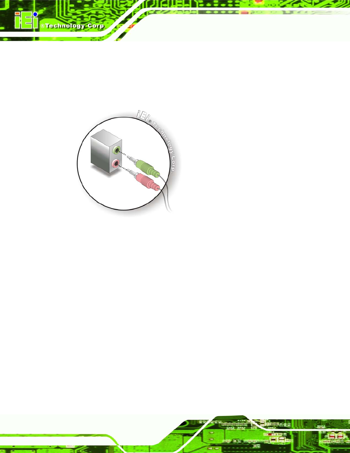
Step 2: Plug the audio plugs into the audio jacks. Plug the audio plugs into the audio
jacks. If the plugs on your speakers are different, an adapter will need to be used
to plug them into the audio jacks.
Line Out port (Lime): Connects to a headphone or a speaker.
Microphone (Pink): Connects to a microphone.
Figure 4-13: Audio Connector
Step 3: Check audio clarity. Check that the sound is coming through the right speakers
by adjusting the balance front to rear and left to right. Step 0:
4.6.2 PS/2 Keyboard and Mouse Connection
The KINO-G410 has a dual PS/2 connector on the external peripheral interface panel. The
dual PS/2 connector is used to connect to a keyboard and mouse to the system. Follow
the steps below to connect a keyboard and mouse to the KINO-G410.
Step 1: Locate the dual PS/2 connector. The location of the dual PS/2 connector is
shown in Chapter 3.
Step 2: Insert the keyboard/mouse connector. Insert a PS/2 keyboard or mouse
connector into the appropriate PS/2 connector on the external peripheral
interface connector. See Figure 4-14.