
Manual
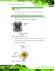


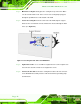

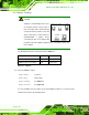
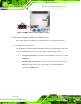

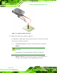
Table Of Contents
- Revision
- Copyright
- Table of Contents
- List of Figures
- List of Tables
- BIOS Menus
- 1 Introduction
- 2 Packing List
- 3 Connectors
- 3.1 Peripheral Interface Connectors
- 3.2 Internal Peripheral Connectors
- 3.2.1 Battery Connector
- 3.2.2 CPU Fan Connector
- 3.2.3 System Fan Connector
- 3.2.4 CPU Power Input Connector
- 3.2.5 Digital I/O Connector
- 3.2.6 Front Panel Connector
- 3.2.7 Memory Slot
- 3.2.8 Parallel Port Connector
- 3.2.9 Power Connector
- 3.2.10 RS-232 Serial Port Connector
- 3.2.11 RS-232/422/485 Serial Port Connector
- 3.2.12 SATA Drive Connectors
- 3.2.13 SMBus Connector
- 3.2.14 SPI Flash Connector
- 3.2.15 USB Connectors
- 3.2.16 VGA to LVDS Connector
- 3.3 External Peripheral Interface Connector Panel
- 4 Installation
- 5 BIOS
- A BIOS Options
- B Terminology
- C One Key Recovery
- D Watchdog Timer
- E Digital I/O Interface
- F Hazardous Materials Disclosure

KINO-G410 Mini-ITX Motherboard
Page 45
Pin Description
Short 1-2 Normal (Default)
Short 2-3 Clear BIOS
Table 4-2: Clear BIOS Jumper Settings
Figure 4-8: Clear BIOS Jumper Location
4.4.2 COM 6 Function Select Jumper
Jumper Label: JP2
Jumper Type:
8-pin header
Jumper Settings:
See Table 4-3
Jumper Location:
See Figure 4-9
The COM 6 Function Select jumper sets the communication protocol used by the second
serial communications port (COM 6) as RS-232, RS-422 or RS-485. The COM 6 Function
Select settings are shown in Table 4-3.
Setting Description
Short 1-2 RS-232 (Default)
Short 3-4 RS-422
Short 5-6 RS-485
Short 7-8 RS-485 with RTS control
Table 4-3: COM 6 Function Select Jumper Settings