
Manual
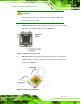


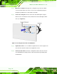


Table Of Contents
- Revision
- Copyright
- Table of Contents
- List of Figures
- List of Tables
- BIOS Menus
- 1 Introduction
- 2 Packing List
- 3 Connectors
- 3.1 Peripheral Interface Connectors
- 3.2 Internal Peripheral Connectors
- 3.2.1 Battery Connector
- 3.2.2 CPU Fan Connector
- 3.2.3 System Fan Connector
- 3.2.4 CPU Power Input Connector
- 3.2.5 Digital I/O Connector
- 3.2.6 Front Panel Connector
- 3.2.7 Memory Slot
- 3.2.8 Parallel Port Connector
- 3.2.9 Power Connector
- 3.2.10 RS-232 Serial Port Connector
- 3.2.11 RS-232/422/485 Serial Port Connector
- 3.2.12 SATA Drive Connectors
- 3.2.13 SMBus Connector
- 3.2.14 SPI Flash Connector
- 3.2.15 USB Connectors
- 3.2.16 VGA to LVDS Connector
- 3.3 External Peripheral Interface Connector Panel
- 4 Installation
- 5 BIOS
- A BIOS Options
- B Terminology
- C One Key Recovery
- D Watchdog Timer
- E Digital I/O Interface
- F Hazardous Materials Disclosure
KINO-G410 Mini-ITX Motherboard
Page 42
Step 3: Mount the cooling kit. Gently place the cooling kit on top of the CPU. Make
sure the four threaded screws on the corners of the cooling kit properly pass
through the predrilled holes on the bottom of the PCB.
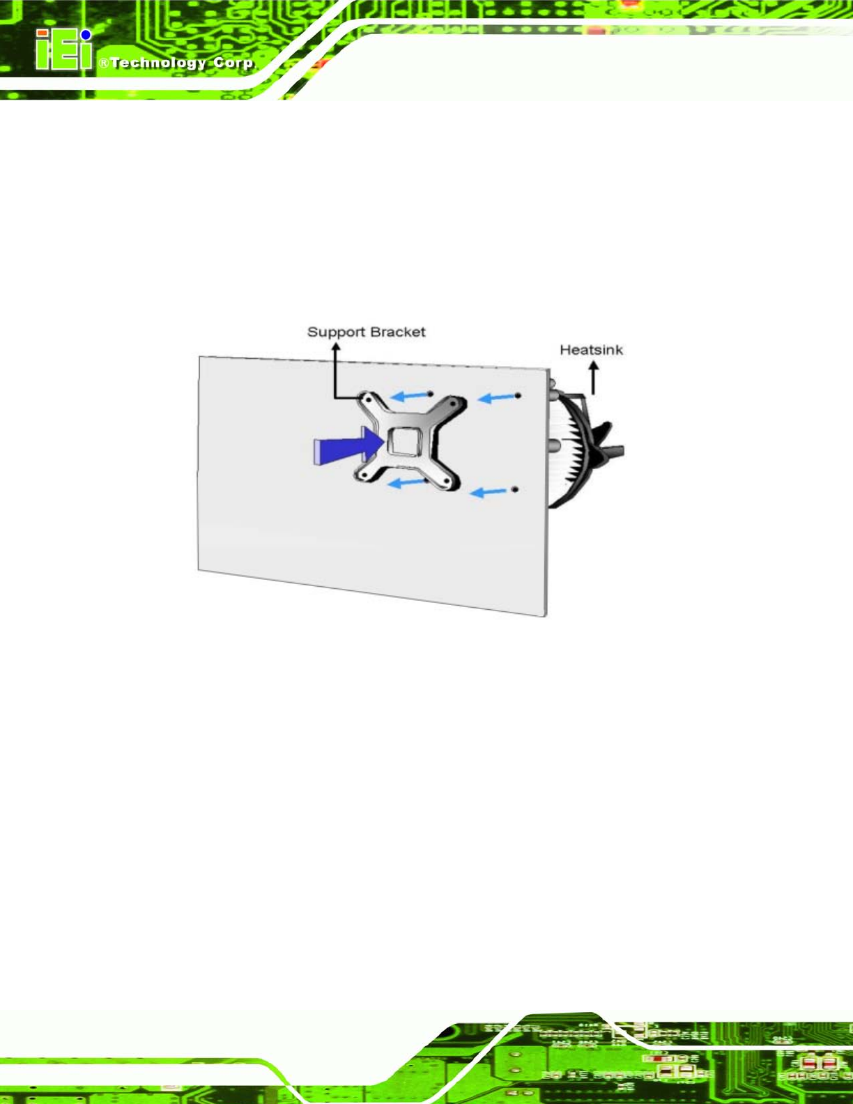
Step 4: Secure the cooling kit. From the solder side of the PCB, align the support
bracket to the screw threads on heat sink that were inserted through the PCB
holes. (See Figure 4-6)
Figure 4-6: Securing the Heat sink to the KINO-G410
Step 5: Tighten the screws. Use a screwdriver to tighten the four screws. Tighten each
nut a few turns at a time and do not over-tighten the screws.
Step 6: Connect the fan cable. Connect the cooling kit fan cable to the fan connector
on the KINO-G410. Carefully route the cable and avoid heat generating chips
and fan blades. Step 0: