
Manual
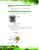


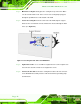


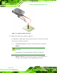
Table Of Contents
- Revision
- Copyright
- Table of Contents
- List of Figures
- List of Tables
- BIOS Menus
- 1 Introduction
- 2 Packing List
- 3 Connectors
- 3.1 Peripheral Interface Connectors
- 3.2 Internal Peripheral Connectors
- 3.2.1 Battery Connector
- 3.2.2 CPU Fan Connector
- 3.2.3 System Fan Connector
- 3.2.4 CPU Power Input Connector
- 3.2.5 Digital I/O Connector
- 3.2.6 Front Panel Connector
- 3.2.7 Memory Slot
- 3.2.8 Parallel Port Connector
- 3.2.9 Power Connector
- 3.2.10 RS-232 Serial Port Connector
- 3.2.11 RS-232/422/485 Serial Port Connector
- 3.2.12 SATA Drive Connectors
- 3.2.13 SMBus Connector
- 3.2.14 SPI Flash Connector
- 3.2.15 USB Connectors
- 3.2.16 VGA to LVDS Connector
- 3.3 External Peripheral Interface Connector Panel
- 4 Installation
- 5 BIOS
- A BIOS Options
- B Terminology
- C One Key Recovery
- D Watchdog Timer
- E Digital I/O Interface
- F Hazardous Materials Disclosure
KINO-G410 Mini-ITX Motherboard
Page 41
4.3.2 Cooling Kit Installation
WARNING:
DO NOT use the original Intel® heat sink and fan. A proprietary one is
recommended.
Figure 4-5: Cooling Kits
The cooling kit can be bought from IEI. The cooling kit has a heatsink and fan.
WARNING:
Do not wipe off (accidentally or otherwise) the pre-sprayed layer of
thermal paste on the bottom of the heat sink. The thermal paste
between the CPU and the heat sink is important for optimum heat
dissipation.
To install the cooling kit, follow the instructions below.
Step 1: Place the cooling kit onto the socket LGA775 CPU. Make sure the CPU
cable can be properly routed when the cooling kit is installed.
Step 2: Properly align the cooling kit. Make sure the four spring screw fasteners can
pass through the pre-drilled holes on the PCB.