
Manual
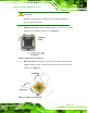


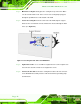


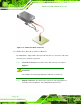
Table Of Contents
- Revision
- Copyright
- Table of Contents
- List of Figures
- List of Tables
- BIOS Menus
- 1 Introduction
- 2 Packing List
- 3 Connectors
- 3.1 Peripheral Interface Connectors
- 3.2 Internal Peripheral Connectors
- 3.2.1 Battery Connector
- 3.2.2 CPU Fan Connector
- 3.2.3 System Fan Connector
- 3.2.4 CPU Power Input Connector
- 3.2.5 Digital I/O Connector
- 3.2.6 Front Panel Connector
- 3.2.7 Memory Slot
- 3.2.8 Parallel Port Connector
- 3.2.9 Power Connector
- 3.2.10 RS-232 Serial Port Connector
- 3.2.11 RS-232/422/485 Serial Port Connector
- 3.2.12 SATA Drive Connectors
- 3.2.13 SMBus Connector
- 3.2.14 SPI Flash Connector
- 3.2.15 USB Connectors
- 3.2.16 VGA to LVDS Connector
- 3.3 External Peripheral Interface Connector Panel
- 4 Installation
- 5 BIOS
- A BIOS Options
- B Terminology
- C One Key Recovery
- D Watchdog Timer
- E Digital I/O Interface
- F Hazardous Materials Disclosure
KINO-G410 Mini-ITX Motherboard
Page 39
WARNING:
DO NOT touch the pins at the bottom of the CPU. When handling the
CPU, only hold it on the sides.
Step 1: Remove the protective cover. The black protective cover can be removed by
pulling up on the tab labeled "Remove". See Figure 4-2.
Figure 4-2: Remove Protective Cover
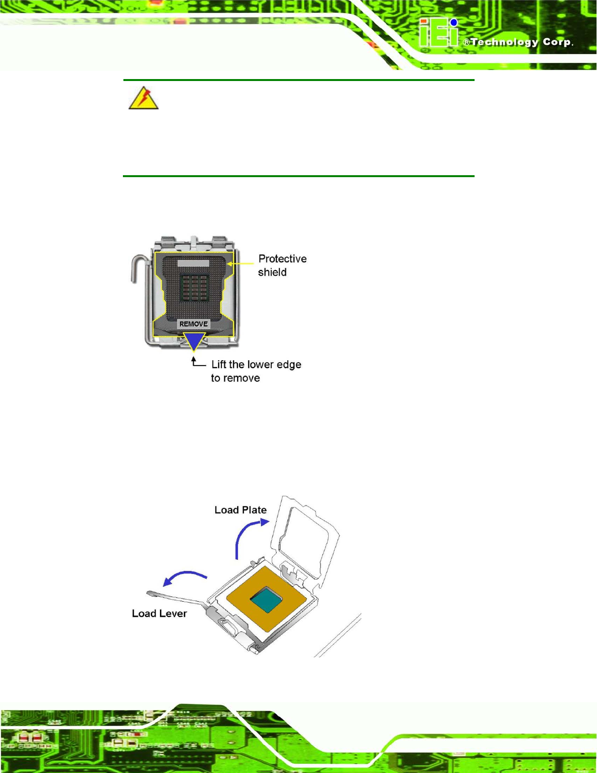
Step 2: Open the socket. Disengage the load lever by pressing the lever down and
slightly outward to clear the retention tab. Fully open the lever, then open the
load plate. See Figure 4-3.
Figure 4-3: CPU Socket Load Plate