
Manual
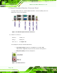
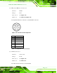
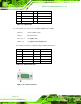
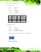
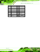

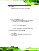
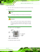
Table Of Contents
- Revision
- Copyright
- Table of Contents
- List of Figures
- List of Tables
- BIOS Menus
- 1 Introduction
- 2 Packing List
- 3 Connectors
- 3.1 Peripheral Interface Connectors
- 3.2 Internal Peripheral Connectors
- 3.2.1 Battery Connector
- 3.2.2 CPU Fan Connector
- 3.2.3 System Fan Connector
- 3.2.4 CPU Power Input Connector
- 3.2.5 Digital I/O Connector
- 3.2.6 Front Panel Connector
- 3.2.7 Memory Slot
- 3.2.8 Parallel Port Connector
- 3.2.9 Power Connector
- 3.2.10 RS-232 Serial Port Connector
- 3.2.11 RS-232/422/485 Serial Port Connector
- 3.2.12 SATA Drive Connectors
- 3.2.13 SMBus Connector
- 3.2.14 SPI Flash Connector
- 3.2.15 USB Connectors
- 3.2.16 VGA to LVDS Connector
- 3.3 External Peripheral Interface Connector Panel
- 4 Installation
- 5 BIOS
- A BIOS Options
- B Terminology
- C One Key Recovery
- D Watchdog Timer
- E Digital I/O Interface
- F Hazardous Materials Disclosure
KINO-G410 Mini-ITX Motherboard
Page 32
Pin Description Pin Description
1 MDIA3- 5 MDIA1+
2 MDIA3+ 6 MDIA2+-
3 MDIA2- 7 MDIA0-
4 MDIA1- 8 MDIA0+
Table 3-18: LAN Pinouts
3.3.4 Serial Port Connectors (COM1, COM2 and COM3)
CN Label: COM1, COM2, COM3
CN Type:
DB-9 connectors
CN Location:
See Figure 3-18
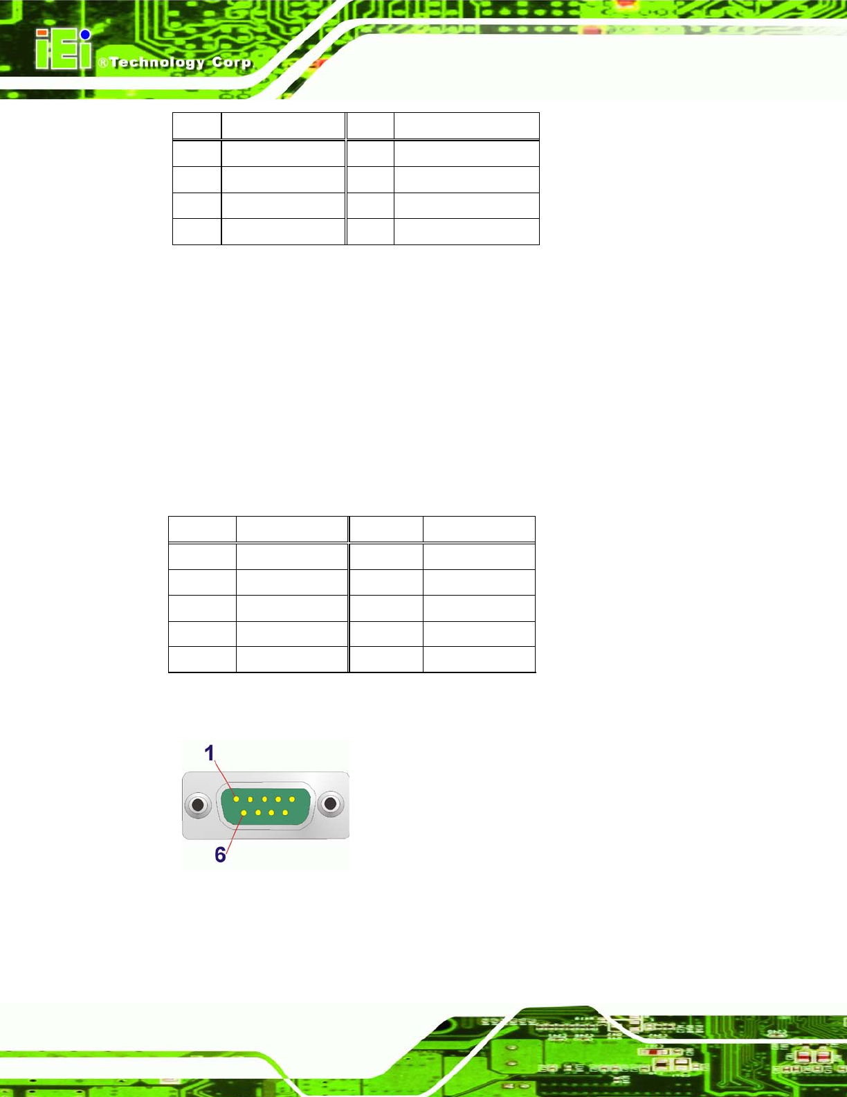
CN Pinouts:
See Table 3-19 and Figure 3-21
The serial port connects to a RS-232 serial communications device.
Pin Description Pin Description
1 DCD 6 DSR
2 RX 7 RTS
3 TX 8 CTS
4 DTR 9 RI
5 GND
Table 3-19: Serial Port Pinouts
Figure 3-21: Serial Port Pinouts