
Manual
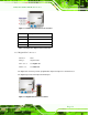
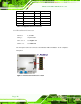
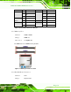
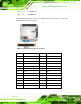


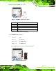
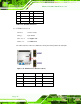
Table Of Contents
- Revision
- Copyright
- Table of Contents
- List of Figures
- List of Tables
- BIOS Menus
- 1 Introduction
- 2 Packing List
- 3 Connectors
- 3.1 Peripheral Interface Connectors
- 3.2 Internal Peripheral Connectors
- 3.2.1 Battery Connector
- 3.2.2 CPU Fan Connector
- 3.2.3 System Fan Connector
- 3.2.4 CPU Power Input Connector
- 3.2.5 Digital I/O Connector
- 3.2.6 Front Panel Connector
- 3.2.7 Memory Slot
- 3.2.8 Parallel Port Connector
- 3.2.9 Power Connector
- 3.2.10 RS-232 Serial Port Connector
- 3.2.11 RS-232/422/485 Serial Port Connector
- 3.2.12 SATA Drive Connectors
- 3.2.13 SMBus Connector
- 3.2.14 SPI Flash Connector
- 3.2.15 USB Connectors
- 3.2.16 VGA to LVDS Connector
- 3.3 External Peripheral Interface Connector Panel
- 4 Installation
- 5 BIOS
- A BIOS Options
- B Terminology
- C One Key Recovery
- D Watchdog Timer
- E Digital I/O Interface
- F Hazardous Materials Disclosure

KINO-G410 Mini-ITX Motherboard
Page 26
3.2.12 S ATA Driv e Connectors
CN Label: SATA1, SATA2, SATA3, SATA4
CN Type:
7-pin SATA drive connectors
CN Location:
See Figure 3-13
The SATA drive connectors can be connected to SATA 3Gb/s drives.
Figure 3-13: SATA Drive Connector Location
3.2.13 S MBu s Connector
CN Label: CN1
CN Type:
4-pin wafer
CN Location:
See Figure 3-14
CN Pinouts:
See Table 3-13
The SMBus (System Management Bus) connector provides low-speed system
management communications.