
Manual
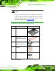

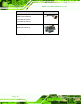

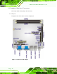
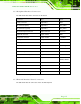


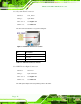
Table Of Contents
- Revision
- Copyright
- Table of Contents
- List of Figures
- List of Tables
- BIOS Menus
- 1 Introduction
- 2 Packing List
- 3 Connectors
- 3.1 Peripheral Interface Connectors
- 3.2 Internal Peripheral Connectors
- 3.2.1 Battery Connector
- 3.2.2 CPU Fan Connector
- 3.2.3 System Fan Connector
- 3.2.4 CPU Power Input Connector
- 3.2.5 Digital I/O Connector
- 3.2.6 Front Panel Connector
- 3.2.7 Memory Slot
- 3.2.8 Parallel Port Connector
- 3.2.9 Power Connector
- 3.2.10 RS-232 Serial Port Connector
- 3.2.11 RS-232/422/485 Serial Port Connector
- 3.2.12 SATA Drive Connectors
- 3.2.13 SMBus Connector
- 3.2.14 SPI Flash Connector
- 3.2.15 USB Connectors
- 3.2.16 VGA to LVDS Connector
- 3.3 External Peripheral Interface Connector Panel
- 4 Installation
- 5 BIOS
- A BIOS Options
- B Terminology
- C One Key Recovery
- D Watchdog Timer
- E Digital I/O Interface
- F Hazardous Materials Disclosure
KINO-G410 Mini-ITX Motherboard
Page 15
3.1.2 Peripheral Interface Connectors
The table below lists all the connectors on the board.
Connector Type Label
Battery connector 2-pin wafer BAT1
Fan connector (CPU) 4-pin wafer CPU_FAN1
Fan connector (system) 3-pin wafer SYS_FAN1
CPU Power Input Connector 4-pin connector CPU12V1
Digital I/O connector 10-pin header DIO1
Front panel connector 14-pin header F_PANEL1
Memory slot 204-pin DDR3 DIMM slot DIMM1, DIMM2
Parallel port connector 26-pin header LPT1
PCIe x16 slot PCIe x16 slot PCIEX16_1
Power connector 24-pin connector ATX1
RS-232 serial port connector 10-pin header COM4, COM5
RS-232/422/485 serial port connector 14-pin header COM6
SATA drive connectors 7-pin SATA drive connectors SATA1, SATA2,
SATA3, SATA4
SMBus connector 4-pin wafer CN1
SPI Flash connector 8-pin header JSPI1
USB connectors 8-pin header USB45, USB67
VGA to LVDS connector 20-pin header JP4
Table 3–1: Internal Peripheral Connectors
3.1.3 External Interface Panel Connectors
The table below lists the connectors on the external I/O panel.