
Manual
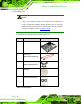

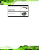


Table Of Contents
- Revision
- Copyright
- Table of Contents
- List of Figures
- List of Tables
- BIOS Menus
- 1 Introduction
- 2 Packing List
- 3 Connectors
- 3.1 Peripheral Interface Connectors
- 3.2 Internal Peripheral Connectors
- 3.2.1 Battery Connector
- 3.2.2 CPU Fan Connector
- 3.2.3 System Fan Connector
- 3.2.4 CPU Power Input Connector
- 3.2.5 Digital I/O Connector
- 3.2.6 Front Panel Connector
- 3.2.7 Memory Slot
- 3.2.8 Parallel Port Connector
- 3.2.9 Power Connector
- 3.2.10 RS-232 Serial Port Connector
- 3.2.11 RS-232/422/485 Serial Port Connector
- 3.2.12 SATA Drive Connectors
- 3.2.13 SMBus Connector
- 3.2.14 SPI Flash Connector
- 3.2.15 USB Connectors
- 3.2.16 VGA to LVDS Connector
- 3.3 External Peripheral Interface Connector Panel
- 4 Installation
- 5 BIOS
- A BIOS Options
- B Terminology
- C One Key Recovery
- D Watchdog Timer
- E Digital I/O Interface
- F Hazardous Materials Disclosure
KINO-G410 Mini-ITX Motherboard
Page 10
2.3 Packing List
NOTE:
If any of the components listed in the checklist below are missing, do
not proceed with the installation. Contact the IEI reseller or vendor the
KINO-G410 was purchased from or contact an IEI sales representative
directly by sending an email to
sales@iei.com.tw.
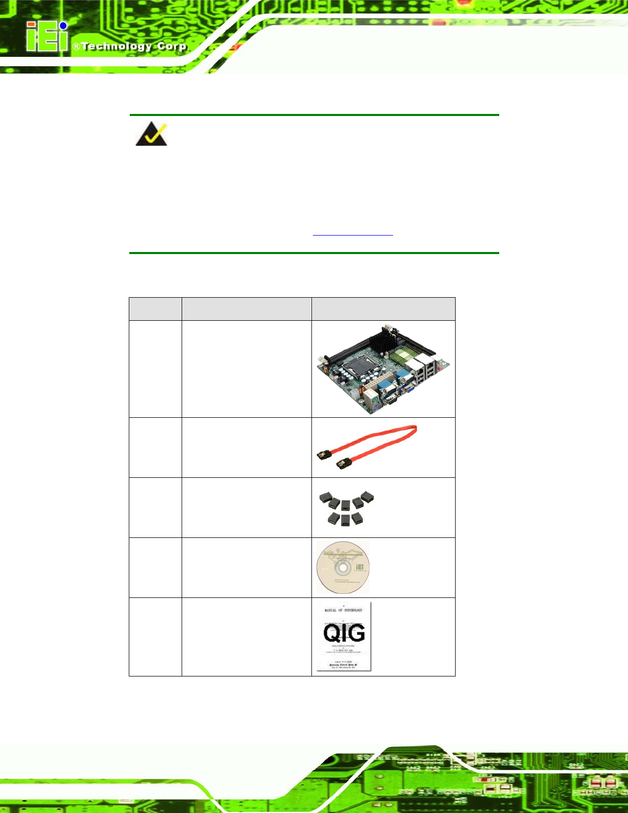
The KINO-G410 is shipped with the following components:
Quantity Item and Part Number Im a g e
1 KINO-G410 SBC
2 SATA cable
(P/N: 32000-062800-RS)
1 Mini jumper pack (2.0mm)
(P/N:33100-000033-RS)
1 Utility CD
1 Quick Installation Guide
Table 2-1: Packing List