
Manual


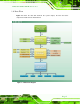
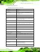
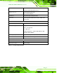

Table Of Contents
- Revision
- Copyright
- Table of Contents
- List of Figures
- List of Tables
- BIOS Menus
- 1 Introduction
- 2 Packing List
- 3 Connectors
- 3.1 Peripheral Interface Connectors
- 3.2 Internal Peripheral Connectors
- 3.2.1 Battery Connector
- 3.2.2 CPU Fan Connector
- 3.2.3 System Fan Connector
- 3.2.4 CPU Power Input Connector
- 3.2.5 Digital I/O Connector
- 3.2.6 Front Panel Connector
- 3.2.7 Memory Slot
- 3.2.8 Parallel Port Connector
- 3.2.9 Power Connector
- 3.2.10 RS-232 Serial Port Connector
- 3.2.11 RS-232/422/485 Serial Port Connector
- 3.2.12 SATA Drive Connectors
- 3.2.13 SMBus Connector
- 3.2.14 SPI Flash Connector
- 3.2.15 USB Connectors
- 3.2.16 VGA to LVDS Connector
- 3.3 External Peripheral Interface Connector Panel
- 4 Installation
- 5 BIOS
- A BIOS Options
- B Terminology
- C One Key Recovery
- D Watchdog Timer
- E Digital I/O Interface
- F Hazardous Materials Disclosure
KINO-G410 Mini-ITX Motherboard
Page 6
1.7 Technical Specifications
KINO-G410 technical specifications are shown below.
Specifications KINO-G410
Form Factor
Mini-ITX
CPU Supported
Socket LGA775 Intel® Core™2 Duo/Quad/Extreme or
Celeron® processor
Front Side Bus (FSB)
800/1066/1333 MHz
Northbridge Chipset
Intel® G41
Me m o ry
Two 240-pin 800/1066 MHz dual-channel DDR3 SDRAM
DIMMs (system max. 4 GB)
Graphic Engine
Intel® GMA4500
Integrated Graphics
VGA integrated in Intel® G41
24-bit LVDS via VGA to LVDS converter module
Southbridge Chipset
Intel® ICH7
BIOS
AMI BIOS
Digital I/O
8-bit, 4-bit input/4-bit output
Ethernet Controllers
Two Realtek RTL8111E PCIe GbE controllers with ASF2.0
support
Super I/O Controller
Fintek F81865
Watchdog Timer
Software programmable supports 1~255 sec. system reset
Audio
Realtek ALC888 HD Audio codec
Expansion
One PCIe x16 socket
I/O In te rfa c e
Audio Jack
One line-out
One mic-in
Fan connector
One 4-pin wafer for CPU fan
One 3-pin wafer for system fan
Keyboard/Mouse
Two external PS/2 connectors