
Manual

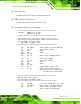


Table Of Contents
- Revision
- Copyright
- Table of Contents
- List of Figures
- List of Tables
- BIOS Menus
- 1 Introduction
- 2 Packing List
- 3 Connectors
- 3.1 Peripheral Interface Connectors
- 3.2 Internal Peripheral Connectors
- 3.2.1 Battery Connector
- 3.2.2 CPU Fan Connector
- 3.2.3 System Fan Connector
- 3.2.4 CPU Power Input Connector
- 3.2.5 Digital I/O Connector
- 3.2.6 Front Panel Connector
- 3.2.7 Memory Slot
- 3.2.8 Parallel Port Connector
- 3.2.9 Power Connector
- 3.2.10 RS-232 Serial Port Connector
- 3.2.11 RS-232/422/485 Serial Port Connector
- 3.2.12 SATA Drive Connectors
- 3.2.13 SMBus Connector
- 3.2.14 SPI Flash Connector
- 3.2.15 USB Connectors
- 3.2.16 VGA to LVDS Connector
- 3.3 External Peripheral Interface Connector Panel
- 4 Installation
- 5 BIOS
- A BIOS Options
- B Terminology
- C One Key Recovery
- D Watchdog Timer
- E Digital I/O Interface
- F Hazardous Materials Disclosure
KINO-G410 Mini-ITX Motherboard
Page 135
E.1 Introduction
The digital I/O is used for machine control and automation.
E.2 DIO Connector Pinouts
Located in the Connectors section of this document.
E.3 Assembly Language Example
;**************************************************
; DIO Port: 0A21h[3:0] (4 Out)
; 0A22h[3:0] (4 In)
;**************************************************
;==================================================
; Get current input and output values into AL register
; AL: bit0~bit3 as output value
; bit4~bit7 as Input value
;==================================================
mov dx, 0A21h ; GPIO output I/O base address
in al, dx ; Get output status
jmp $+2 ; Wait
jmp $+2 ; Wait
and al, 0Fh
mov bl, al ; Move al to bl temporarily
inc dx ; sets dx to 0A22h
in al, dx ; Get input status
jmp $+2 ; Wait
jmp $+2 ; Wait
and al, 0Fh
rol al, 4 ; Shift input values over
or al, bl ; Merge all results into AL
; AL: bit0~bit3 as output value
; bit4~bit7 as input value
;==================================================
; Output value (x) to GPIO
; AL: bit0~bit3 as output value
;==================================================
mov al, 0xh ; x is the output value (0 ~ Fh)
mov dx, 0A21h ; GPIO output I/O base address
out dx, al ; bit0 ~ bit3 as Output value
; bit4 ~ bit7 are Reserved