
Manual
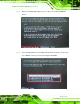

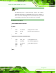
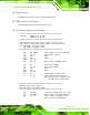


Table Of Contents
- Revision
- Copyright
- Table of Contents
- List of Figures
- List of Tables
- BIOS Menus
- 1 Introduction
- 2 Packing List
- 3 Connectors
- 3.1 Peripheral Interface Connectors
- 3.2 Internal Peripheral Connectors
- 3.2.1 Battery Connector
- 3.2.2 CPU Fan Connector
- 3.2.3 System Fan Connector
- 3.2.4 CPU Power Input Connector
- 3.2.5 Digital I/O Connector
- 3.2.6 Front Panel Connector
- 3.2.7 Memory Slot
- 3.2.8 Parallel Port Connector
- 3.2.9 Power Connector
- 3.2.10 RS-232 Serial Port Connector
- 3.2.11 RS-232/422/485 Serial Port Connector
- 3.2.12 SATA Drive Connectors
- 3.2.13 SMBus Connector
- 3.2.14 SPI Flash Connector
- 3.2.15 USB Connectors
- 3.2.16 VGA to LVDS Connector
- 3.3 External Peripheral Interface Connector Panel
- 4 Installation
- 5 BIOS
- A BIOS Options
- B Terminology
- C One Key Recovery
- D Watchdog Timer
- E Digital I/O Interface
- F Hazardous Materials Disclosure
KINO-G410 Mini-ITX Motherboard
Page 133
NOTE:
The Watchdog Timer is activated through software. The software
application that activates the Watchdog Timer must also deactivate it
when closed. If the Watchdog Timer is not deactivated, the system will
automatically restart after the Timer has finished its countdown.
EXAMP LE P ROGRAM:
; INITIAL TIMER PERIOD COUNTER
;
W_LOOP:
;
MOV AX, 6F02H ;setting the time-out value
MOV BL, 30 ;time-out value is 48 seconds
INT 15H
;
; ADD THE APPLICATION PROGRAM HERE
;
CMP EXIT_AP, 1 ;is the application over?
JNE W_LOOP ;No, restart the application
MOV AX, 6F02H ;disable Watchdog Timer
MOV BL, 0 ;
INT 15H
;
; EXIT ;