
Manual
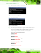

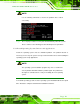
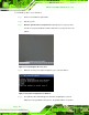
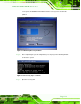

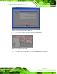
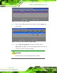
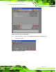
Table Of Contents
- Revision
- Copyright
- Table of Contents
- List of Figures
- List of Tables
- BIOS Menus
- 1 Introduction
- 2 Packing List
- 3 Connectors
- 3.1 Peripheral Interface Connectors
- 3.2 Internal Peripheral Connectors
- 3.2.1 Battery Connector
- 3.2.2 CPU Fan Connector
- 3.2.3 System Fan Connector
- 3.2.4 CPU Power Input Connector
- 3.2.5 Digital I/O Connector
- 3.2.6 Front Panel Connector
- 3.2.7 Memory Slot
- 3.2.8 Parallel Port Connector
- 3.2.9 Power Connector
- 3.2.10 RS-232 Serial Port Connector
- 3.2.11 RS-232/422/485 Serial Port Connector
- 3.2.12 SATA Drive Connectors
- 3.2.13 SMBus Connector
- 3.2.14 SPI Flash Connector
- 3.2.15 USB Connectors
- 3.2.16 VGA to LVDS Connector
- 3.3 External Peripheral Interface Connector Panel
- 4 Installation
- 5 BIOS
- A BIOS Options
- B Terminology
- C One Key Recovery
- D Watchdog Timer
- E Digital I/O Interface
- F Hazardous Materials Disclosure
KINO-G410 Mini-ITX Motherboard
Page 116
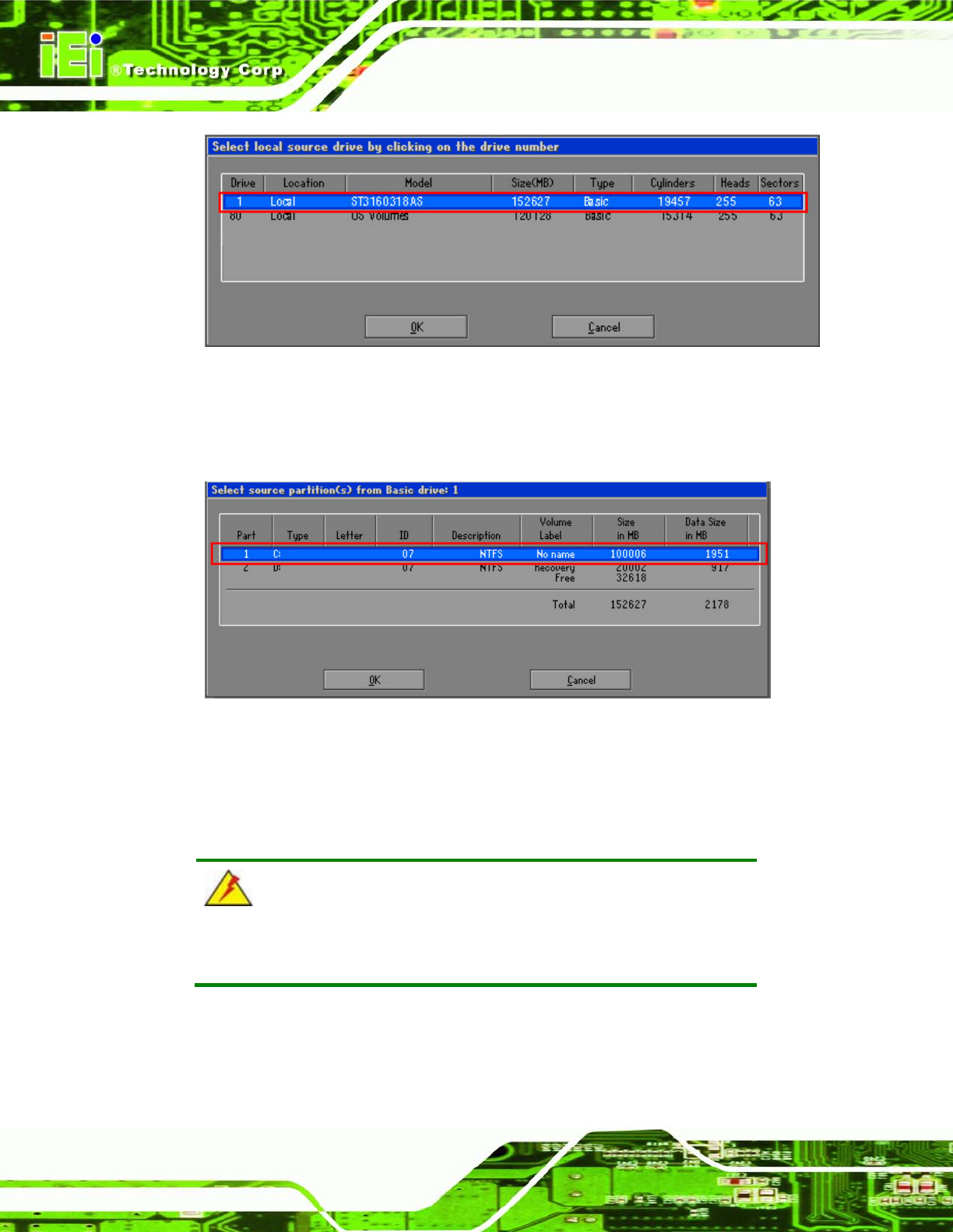
Figure C-14: Select a Local Source Drive
Step 6: Select a source partition (Part 1) from basic drive as shown in Figure C-15.
Then click OK.
Figure C-15: Select a Source Partition from Basic Drive
Step 7: Select 1.2: [Recovery] NTFS drive and enter a file name called iei
(Figure C-16). Click Save. The factory default image will then be saved in the
selected recovery drive and named IEI.GHO.
WARNING:
The file name of the factory default image must be iei.GHO.