
Manual
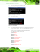

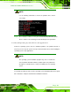
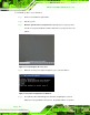
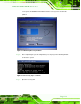

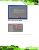
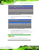
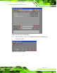
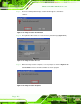
Table Of Contents
- Revision
- Copyright
- Table of Contents
- List of Figures
- List of Tables
- BIOS Menus
- 1 Introduction
- 2 Packing List
- 3 Connectors
- 3.1 Peripheral Interface Connectors
- 3.2 Internal Peripheral Connectors
- 3.2.1 Battery Connector
- 3.2.2 CPU Fan Connector
- 3.2.3 System Fan Connector
- 3.2.4 CPU Power Input Connector
- 3.2.5 Digital I/O Connector
- 3.2.6 Front Panel Connector
- 3.2.7 Memory Slot
- 3.2.8 Parallel Port Connector
- 3.2.9 Power Connector
- 3.2.10 RS-232 Serial Port Connector
- 3.2.11 RS-232/422/485 Serial Port Connector
- 3.2.12 SATA Drive Connectors
- 3.2.13 SMBus Connector
- 3.2.14 SPI Flash Connector
- 3.2.15 USB Connectors
- 3.2.16 VGA to LVDS Connector
- 3.3 External Peripheral Interface Connector Panel
- 4 Installation
- 5 BIOS
- A BIOS Options
- B Terminology
- C One Key Recovery
- D Watchdog Timer
- E Digital I/O Interface
- F Hazardous Materials Disclosure
KINO-G410 Mini-ITX Motherboard
Page 109
Step 3: The recovery tool setup menu is shown as below.
Figure C-3: Recovery Tool Setup Menu
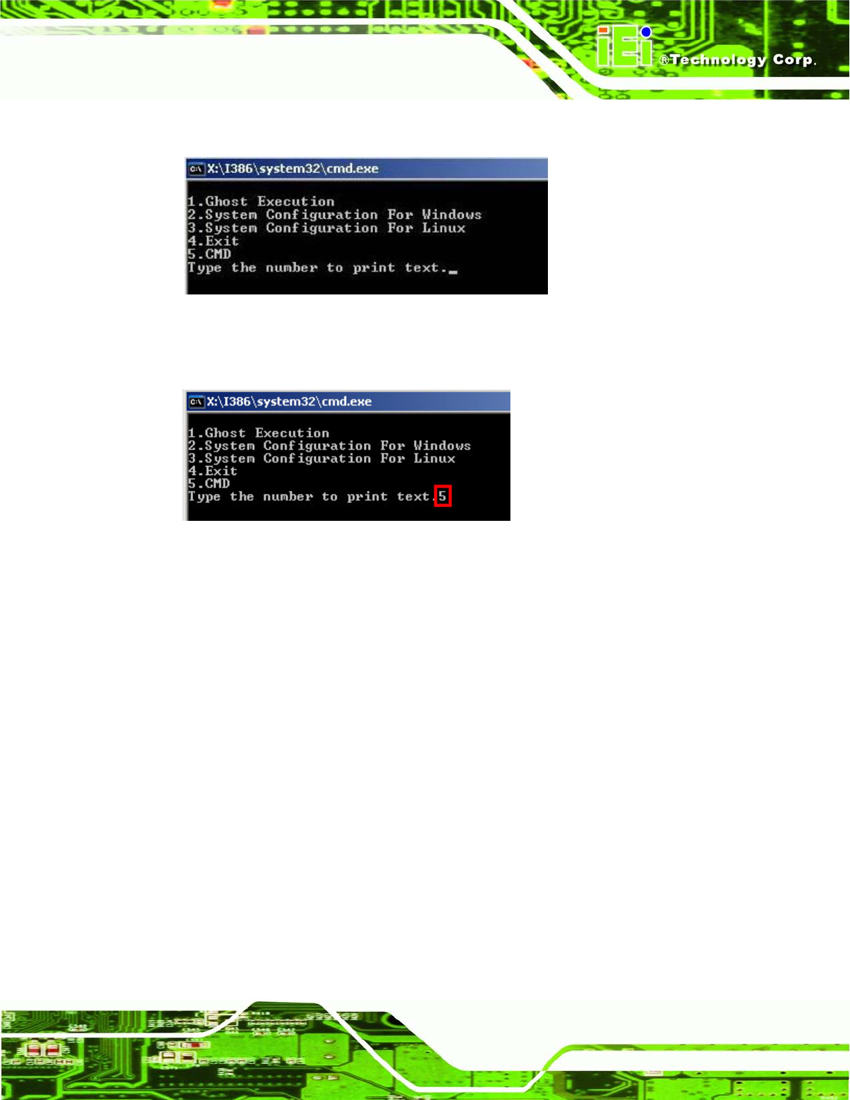
Step 4: Press <5> then <Enter>.
Figure C-4: Command Mode
Step 5: The command prompt window appears. Type the following commands (marked
in red) to create two partitions. One is for the OS installation; the other is for
saving recovery files and images which will be an invisible partition.
(Press <Enter> after entering each line below)
system32>diskpart
DISKPART>list vol
DISKPART>sel disk 0
DISKPART>create part pri size= ___
DISKPART>assign letter=N
DISKPART>create part pri size= ___
DISKPART>assign letter=F
DISKPART>exit
system32>format N: /fs:ntfs /q /y