
Manual

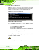
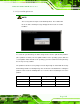
Table Of Contents
- Revision
- Copyright
- Table of Contents
- List of Figures
- List of Tables
- BIOS Menus
- 1 Introduction
- 2 Packing List
- 3 Connectors
- 3.1 Peripheral Interface Connectors
- 3.2 Internal Peripheral Connectors
- 3.2.1 Battery Connector
- 3.2.2 CPU Fan Connector
- 3.2.3 System Fan Connector
- 3.2.4 CPU Power Input Connector
- 3.2.5 Digital I/O Connector
- 3.2.6 Front Panel Connector
- 3.2.7 Memory Slot
- 3.2.8 Parallel Port Connector
- 3.2.9 Power Connector
- 3.2.10 RS-232 Serial Port Connector
- 3.2.11 RS-232/422/485 Serial Port Connector
- 3.2.12 SATA Drive Connectors
- 3.2.13 SMBus Connector
- 3.2.14 SPI Flash Connector
- 3.2.15 USB Connectors
- 3.2.16 VGA to LVDS Connector
- 3.3 External Peripheral Interface Connector Panel
- 4 Installation
- 5 BIOS
- A BIOS Options
- B Terminology
- C One Key Recovery
- D Watchdog Timer
- E Digital I/O Interface
- F Hazardous Materials Disclosure
KINO-G410 Mini-ITX Motherboard
Page 108
Step 4: Turn on the system.
Step 5: Press the <DELETE> key as soon as the system is turned on to enter the BIOS.
Step 6: Select the connected optical disk drive as the 1
st
boot device. (Boot Boot
Device Priority 1
st
Boot Device).
Step 7: Save changes and restart the computer. Continue to the next section for
instructions on partitioning the internal storage. St ep 0:
C.2.2 Create Partitions
To create the system backup, the main storage device must be split into two partitions
(three partitions for Linux). The first partition will be for the operating system, while the
second partition will be invisible to the operating system and contain the backup made by
the one key recovery software.
Step 1: Put the recovery CD in the optical drive of the system.
Step 2: Boot the system from recovery CD. When prompted, press any key to boot
from the recovery CD. It will take a while to launch the recovery tool. Please be
patient!
Figure C-2: Launching the Recovery Tool