
Manual

Table Of Contents
- Revision
- Copyright
- Table of Contents
- List of Figures
- List of Tables
- BIOS Menus
- 1 Introduction
- 2 Packing List
- 3 Connectors
- 3.1 Peripheral Interface Connectors
- 3.2 Internal Peripheral Connectors
- 3.2.1 Battery Connector
- 3.2.2 CPU Fan Connector
- 3.2.3 System Fan Connector
- 3.2.4 CPU Power Input Connector
- 3.2.5 Digital I/O Connector
- 3.2.6 Front Panel Connector
- 3.2.7 Memory Slot
- 3.2.8 Parallel Port Connector
- 3.2.9 Power Connector
- 3.2.10 RS-232 Serial Port Connector
- 3.2.11 RS-232/422/485 Serial Port Connector
- 3.2.12 SATA Drive Connectors
- 3.2.13 SMBus Connector
- 3.2.14 SPI Flash Connector
- 3.2.15 USB Connectors
- 3.2.16 VGA to LVDS Connector
- 3.3 External Peripheral Interface Connector Panel
- 4 Installation
- 5 BIOS
- A BIOS Options
- B Terminology
- C One Key Recovery
- D Watchdog Timer
- E Digital I/O Interface
- F Hazardous Materials Disclosure
KINO-G410 Mini-ITX Motherboard
Page 105
C.1.1 System Requirement
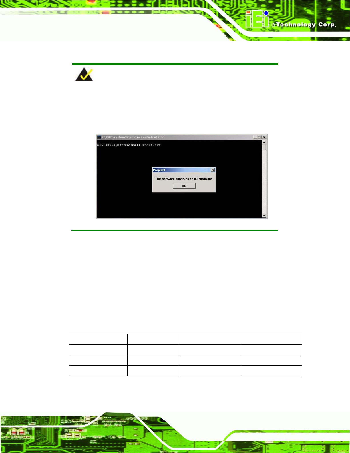
NOTE:
The recovery CD can only be used with IEI products. The software will
fail to run and a warning message will appear when used on non-IEI
hardware.
To create the system backup, the main storage device must be split into two partitions
(three partitions for Linux). The first partition will be for the operating system, while the
second partition will be invisible to the operating system and contain the backup made by
the one key recovery software.
The partition created for recovery images must be big enough to contain both the factory
default image and the user backup image. The size must be calculated before creating the
partitions. Please take the following table as a reference when calculating the size of the
partition.
OS OS Image after Ghost Compression Ratio
Windows® 7 7 GB 5 GB 70%
Windows® XPE 776 MB 560 MB 70%
Windows® CE 6.0 36 MB 28 MB 77%