
Manual

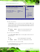
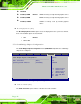


Table Of Contents
- Revision
- Copyright
- Table of Contents
- List of Figures
- List of Tables
- BIOS Menus
- 1 Introduction
- 2 Packing List
- 3 Connectors
- 3.1 Peripheral Interface Connectors
- 3.2 Internal Peripheral Connectors
- 3.2.1 Battery Connector
- 3.2.2 CPU Fan Connector
- 3.2.3 System Fan Connector
- 3.2.4 CPU Power Input Connector
- 3.2.5 Digital I/O Connector
- 3.2.6 Front Panel Connector
- 3.2.7 Memory Slot
- 3.2.8 Parallel Port Connector
- 3.2.9 Power Connector
- 3.2.10 RS-232 Serial Port Connector
- 3.2.11 RS-232/422/485 Serial Port Connector
- 3.2.12 SATA Drive Connectors
- 3.2.13 SMBus Connector
- 3.2.14 SPI Flash Connector
- 3.2.15 USB Connectors
- 3.2.16 VGA to LVDS Connector
- 3.3 External Peripheral Interface Connector Panel
- 4 Installation
- 5 BIOS
- A BIOS Options
- B Terminology
- C One Key Recovery
- D Watchdog Timer
- E Digital I/O Interface
- F Hazardous Materials Disclosure
KINO-G410 Mini-ITX Motherboard
Page 90
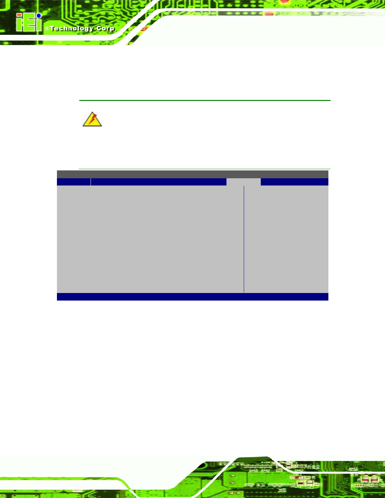
5.7 Chips et
Use the Chipset menu (BIOS Menu 17) to access the NorthBridge and SouthBridge
configuration menus.
WARNING!
Setting the wrong values for the Chipset BIOS selections in the Chipset BIOS
menu may cause the system to malfunction.
BIOS SETUP UTILITY
Main
Advanced
PCIPnP
Boot
Security
Chipset
Exit
Advanced Chipset Settings
WARNING: Setting wrong values in below section
may cause system to malfunction.
> North Bridge Configuration
> South Bridge Configuration
Configure North Bridge
features
Select Screen
↑ ↓ Select Item
Enter Go to Sub Screen
F1 General Help
F10 Save and Exit
ESC Exit
v02.61 ©Copyright 1985-2006, American Megatrends, Inc.
BIOS Menu 17: Chipset
5.7.1 North Bridge Chipset Configuration
Use the North Bridge Chipset Configuration menu (BIOS Menu 18) to configure the
Northbridge chipset settings.