
User guide
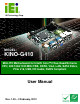


KINO-G410 Mini-ITX Motherboard
Page viii
List of Figures
Figure 1-1: KINO-G410 ...................................................................................................................2
Figure 1-2: Connectors ..................................................................................................................3
Figure 1-3: Dimensions (mm)........................................................................................................4
Figure 1-4: Data Flow Diagram......................................................................................................5
Figure 3-1: Connectors and Jumpers.........................................................................................14
Figure 3-2: Battery Connector Location.....................................................................................16
Figure 3-3: CPU Fan Connector Location ..................................................................................17
Figure 3-4: CPU Fan Connector Location ..................................................................................18
Figure 3-5: CPU Power Input Connector Location....................................................................19
Figure 3-6: Digital I/O Connector Locations ..............................................................................19
Figure 3-7: Front Panel Connector Location .............................................................................20
Figure 3-8: Memory Card Slot Location .....................................................................................21
Figure 3-9: Parallel Port Connector Location............................................................................22
Figure 3-10: Power Connector Location ....................................................................................23
Figure 3-11: Serial Port Connector Location.............................................................................24
Figure 3-12: RS-232/422/485 Serial Port Connector Location..................................................25
Figure 3-13: SATA Drive Connector Location ...........................................................................26
Figure 3-14: SMBus Connector Location...................................................................................27
Figure 3-15: SPI Flash Connector...............................................................................................27
Figure 3-16: USB Connector Pinout Locations .........................................................................28
Figure 3-17: VGA to LVDS Connector Location ........................................................................29
Figure 3-18: External Peripheral Interface Connector ..............................................................30
Figure 3-19: Audio Connector.....................................................................................................30
Figure 3-20: PS/2 Pinouts ............................................................................................................31
Figure 3-21: Serial Port Pinouts..................................................................................................33
Figure 3-22: VGA Connector .......................................................................................................34
Figure 4-1: Intel LGA775 Socket .................................................................................................38
Figure 4-2: Remove Protective Cover.........................................................................................39
Figure 4-3: CPU Socket Load Plate.............................................................................................39
Figure 4-4: Insert the Socket LGA775 CPU................................................................................40