
User guide


KINO-G410 Mini-ITX Motherboard
Page 29
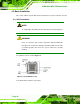
3.2.16 VGA to LVDS Connector
CN Label: JP4
CN Type:
20-pin header
CN Location:
See
Figure 3-17
CN Pinouts:
See
Table 3-16
This connector connects to the optional VGA to LVDS converter module and provides the
24-bit LVDS interface.
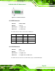
Figure 3-17: VGA to LVDS Connector Location
Pin Description Pin Description
1 GND 2 +5V
3 H-SYNCBUF-OUT_R 4 NC
5 V-SYNCBUF-OUT_R 6 +5V
7 GND 8 GND
9 CH1BUF-OUT_RED 10 +3.3V
11 CH1BUF-OUT_GREEN
12 +3.3V
13 CH1BUF-OUT_BLUE 14 +3.3V
15 GND 16 GND
17 5VDDCDA 18 +12V
19 5VDDCCLK 20 +12V
Table 3-16: VGA to LVDS Connector Pinouts