
User guide


KINO-G410 Mini-ITX Motherboard
Page 21
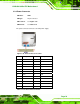
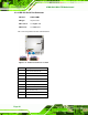
FUNCTION PIN DESCRIPTION FUNCTION PIN DESCRIPTION
1 LED+ 2 BEEP_PWR
3 NC 4 NC
Power LED
5 LED- 6 NC
7 BUTTON1
Buzzer
8 PC_BEEP
Power
Button
9 BUTTON2
-- 10 NC
11 HDD LED+ 12 RESET HDD LED
13 HDD LED-
Reset
14 GND
Table 3-8: Front Panel Connector Pinouts
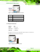
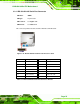
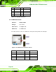
3.2.7 Memory Slot
CN Label: DIMM1, DIMM2
CN Type:
DIMM slot
CN Location:
See
Figure 3-8
The DIMM slots are for DIMM memory modules.
Figure 3-8: Memory Card Slot Location
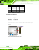
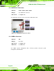
3.2.8 Parallel Port Connector
CN Label: LPT1
CN Type:
26-pin header