
User guide


KINO-G410 Mini-ITX Motherboard
Page 20
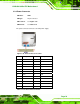
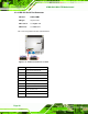
Pin Description Pin Description
1 GND 2 VCC5S
3 Output 3 4 Output 2
5 Output 1 6 Output 0
7 Input 3 8 Input 2
9 Input 1 10 Input 0
Table 3-7: Digital I/O Connector Pinouts
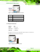
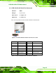
3.2.6 Front Panel Connector
CN Label: F_PANEL1
CN Type:
14-pin header
CN Location:
See
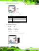
Figure 3-7
CN Pinouts:
See
Table 3-8
The front panel connector connects to the indicator LEDs and buttons on the computer's
front panel.
Figure 3-7: Front Panel Connector Location