
Manual


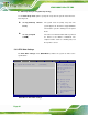
Table Of Contents
- 1 Introduction
- 2 Packing List
- 3 Connector Pinouts
- 3.1 Peripheral Interface Connectors
- 3.2 Internal Peripheral Connectors
- 3.2.1 ATX Power Signal Connector
- 3.2.2 Battery Connector
- 3.2.3 Digital I/O Connector
- 3.2.4 DisplayPort Connector
- 3.2.5 EC Debug Port
- 3.2.6 Fan Connector (CPU)
- 3.2.7 Fan Connector (System)
- 3.2.8 Front Panel Connector
- 3.2.9 Keyboard/Mouse Connector
- 3.2.10 LAN Active LED Connector
- 3.2.11 LVDS Connector
- 3.2.12 LVDS Backlight Connector
- 3.2.13 PCIe Mini Card Slot (Full-size)
- 3.2.14 PCIe Mini Card Slot (Half-size)
- 3.2.15 PCI Express x16 Slot
- 3.2.16 Power Button (On-board)
- 3.2.17 Power Connector (12V)
- 3.2.18 RS-232 Serial Port Connectors (COM2 ~ COM5)
- 3.2.19 RS-422/485 Serial Port Connector (COM6)
- 3.2.20 SATA 6Gb/s Drive Connectors
- 3.2.21 SATA 3Gb/s Drive Connectors
- 3.2.22 SATA Power Connectors
- 3.2.23 SMBus Connector
- 3.2.24 SO-DIMM Connectors
- 3.2.25 SPI Flash Connector
- 3.2.26 SPI Flash Connector (EC)
- 3.2.27 TPM Connector
- 3.2.28 USB 2.0 Connectors
- 3.2.29 USB 3.0/2.0 Connector
- 3.3 External Interface Connectors
- 4 Installation
- 4.1 Anti-static Precautions
- 4.2 Installation Considerations
- 4.3 Cooling Kit Installation
- 4.4 SO-DIMM Installation
- 4.5 PCIe Mini Card Installation
- 4.6 Jumper Settings
- 4.7 Chassis Installation
- 4.8 Internal Peripheral Device Connections
- 4.9 External Peripheral Interface Connection
- 4.10 Intel® AMT Setup Procedure
- 5 BIOS
- 5.1 Introduction
- 5.2 Main
- 5.3 Advanced
- 5.3.1 ACPI Settings
- 5.3.2 RTC Wake Settings
- 5.3.3 Trusted Computing
- 5.3.4 CPU Configuration
- 5.3.5 SATA Configuration
- 5.3.6 Intel(R) Rapid Start Technology
- 5.3.7 AMT Configuration
- 5.3.8 USB Configuration
- 5.3.9 iWDD H/W Monitor
- 5.3.10 F81866 Super IO Configuration
- 5.3.11 F81866 H/W Monitor
- 5.3.12 Serial Port Console Redirection
- 5.3.13 iEi Feature
- 5.4 Chipset
- 5.5 Boot
- 5.6 Security
- 5.7 Save & Exit
- 6 Software Drivers
- A BIOS Options
- B One Key Recovery
- C Terminology
- D Digital I/O Interface
- E Hazardous Materials Disclosure
KINO-DQM871 Mini-ITX SBC
Page 78
5.1 Introduction
The BIOS is programmed onto the BIOS chip. The BIOS setup program allows changes to
certain system settings. This chapter outlines the options that can be changed.
NOTE:
Some of the BIOS options may vary throughout the life cycle of the
product and are subject to change without prior notice.
5.1.1 Starting Setup
The UEFI BIOS is activated when the computer is turned on. The setup program can be
activated in one of two ways.
1. Press the DEL or F2 key as soon as the system is turned on or
2. Press the DEL or F2 key when the “Press DEL or F2 to enter SETUP”
message appears on the screen.
If the message disappears before the DEL or F2 key is pressed, restart the computer and
try again.
5.1.2 Using Setup
Use the arrow keys to highlight items, press ENTER to select, use the PageUp and
PageDown keys to change entries, press F1 for help and press E
SC to quit. Navigation
keys are shown in the following table.
Key Function
Up arrow Move to previous item
Down arrow Move to next item