
Manual


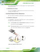


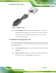


Table Of Contents
- 1 Introduction
- 2 Packing List
- 3 Connector Pinouts
- 3.1 Peripheral Interface Connectors
- 3.2 Internal Peripheral Connectors
- 3.2.1 ATX Power Signal Connector
- 3.2.2 Battery Connector
- 3.2.3 Digital I/O Connector
- 3.2.4 DisplayPort Connector
- 3.2.5 EC Debug Port
- 3.2.6 Fan Connector (CPU)
- 3.2.7 Fan Connector (System)
- 3.2.8 Front Panel Connector
- 3.2.9 Keyboard/Mouse Connector
- 3.2.10 LAN Active LED Connector
- 3.2.11 LVDS Connector
- 3.2.12 LVDS Backlight Connector
- 3.2.13 PCIe Mini Card Slot (Full-size)
- 3.2.14 PCIe Mini Card Slot (Half-size)
- 3.2.15 PCI Express x16 Slot
- 3.2.16 Power Button (On-board)
- 3.2.17 Power Connector (12V)
- 3.2.18 RS-232 Serial Port Connectors (COM2 ~ COM5)
- 3.2.19 RS-422/485 Serial Port Connector (COM6)
- 3.2.20 SATA 6Gb/s Drive Connectors
- 3.2.21 SATA 3Gb/s Drive Connectors
- 3.2.22 SATA Power Connectors
- 3.2.23 SMBus Connector
- 3.2.24 SO-DIMM Connectors
- 3.2.25 SPI Flash Connector
- 3.2.26 SPI Flash Connector (EC)
- 3.2.27 TPM Connector
- 3.2.28 USB 2.0 Connectors
- 3.2.29 USB 3.0/2.0 Connector
- 3.3 External Interface Connectors
- 4 Installation
- 4.1 Anti-static Precautions
- 4.2 Installation Considerations
- 4.3 Cooling Kit Installation
- 4.4 SO-DIMM Installation
- 4.5 PCIe Mini Card Installation
- 4.6 Jumper Settings
- 4.7 Chassis Installation
- 4.8 Internal Peripheral Device Connections
- 4.9 External Peripheral Interface Connection
- 4.10 Intel® AMT Setup Procedure
- 5 BIOS
- 5.1 Introduction
- 5.2 Main
- 5.3 Advanced
- 5.3.1 ACPI Settings
- 5.3.2 RTC Wake Settings
- 5.3.3 Trusted Computing
- 5.3.4 CPU Configuration
- 5.3.5 SATA Configuration
- 5.3.6 Intel(R) Rapid Start Technology
- 5.3.7 AMT Configuration
- 5.3.8 USB Configuration
- 5.3.9 iWDD H/W Monitor
- 5.3.10 F81866 Super IO Configuration
- 5.3.11 F81866 H/W Monitor
- 5.3.12 Serial Port Console Redirection
- 5.3.13 iEi Feature
- 5.4 Chipset
- 5.5 Boot
- 5.6 Security
- 5.7 Save & Exit
- 6 Software Drivers
- A BIOS Options
- B One Key Recovery
- C Terminology
- D Digital I/O Interface
- E Hazardous Materials Disclosure

KINO-DQM871 Mini-ITX SBC
Page 69
Step 3: Connect the cable to the SATA disk. Connect the connector on the other end
of the cable to the connector at the back of the SATA drive. See
Figure 4-10.
Step 4: To remove the SATA cable from the SATA connector, press the clip on the
connector at the end of the cable. Step 0:
4.9 External Peripheral Interface Connection
Devices can be connected to the external connectors. To install external devices, follow
the directions in the subsections below.
4.9.1 Audio Connector
The audio jacks on the external audio connector enable the KINO-DQM871 to be
connected to a stereo sound setup. To install the audio devices, follow the steps below.
Step 1: Identify the audio plugs. The plugs on your home theater system or speakers
may not match the colors on the rear panel. If audio plugs are plugged into the
wrong jacks, sound quality will be very bad.
Step 2: Plug the audio plugs into the audio jacks. Plug the audio plugs into the audio
jacks. If the plugs on your speakers are different, an adapter will need to be used
to plug them into the audio jacks.
Line Out port (Lime): Connects to a headphone or a speaker.
Microphone (Pink): Connects to a microphone.