
Manual
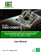


Table Of Contents
- 1 Introduction
- 2 Packing List
- 3 Connector Pinouts
- 3.1 Peripheral Interface Connectors
- 3.2 Internal Peripheral Connectors
- 3.2.1 ATX Power Signal Connector
- 3.2.2 Battery Connector
- 3.2.3 Digital I/O Connector
- 3.2.4 DisplayPort Connector
- 3.2.5 EC Debug Port
- 3.2.6 Fan Connector (CPU)
- 3.2.7 Fan Connector (System)
- 3.2.8 Front Panel Connector
- 3.2.9 Keyboard/Mouse Connector
- 3.2.10 LAN Active LED Connector
- 3.2.11 LVDS Connector
- 3.2.12 LVDS Backlight Connector
- 3.2.13 PCIe Mini Card Slot (Full-size)
- 3.2.14 PCIe Mini Card Slot (Half-size)
- 3.2.15 PCI Express x16 Slot
- 3.2.16 Power Button (On-board)
- 3.2.17 Power Connector (12V)
- 3.2.18 RS-232 Serial Port Connectors (COM2 ~ COM5)
- 3.2.19 RS-422/485 Serial Port Connector (COM6)
- 3.2.20 SATA 6Gb/s Drive Connectors
- 3.2.21 SATA 3Gb/s Drive Connectors
- 3.2.22 SATA Power Connectors
- 3.2.23 SMBus Connector
- 3.2.24 SO-DIMM Connectors
- 3.2.25 SPI Flash Connector
- 3.2.26 SPI Flash Connector (EC)
- 3.2.27 TPM Connector
- 3.2.28 USB 2.0 Connectors
- 3.2.29 USB 3.0/2.0 Connector
- 3.3 External Interface Connectors
- 4 Installation
- 4.1 Anti-static Precautions
- 4.2 Installation Considerations
- 4.3 Cooling Kit Installation
- 4.4 SO-DIMM Installation
- 4.5 PCIe Mini Card Installation
- 4.6 Jumper Settings
- 4.7 Chassis Installation
- 4.8 Internal Peripheral Device Connections
- 4.9 External Peripheral Interface Connection
- 4.10 Intel® AMT Setup Procedure
- 5 BIOS
- 5.1 Introduction
- 5.2 Main
- 5.3 Advanced
- 5.3.1 ACPI Settings
- 5.3.2 RTC Wake Settings
- 5.3.3 Trusted Computing
- 5.3.4 CPU Configuration
- 5.3.5 SATA Configuration
- 5.3.6 Intel(R) Rapid Start Technology
- 5.3.7 AMT Configuration
- 5.3.8 USB Configuration
- 5.3.9 iWDD H/W Monitor
- 5.3.10 F81866 Super IO Configuration
- 5.3.11 F81866 H/W Monitor
- 5.3.12 Serial Port Console Redirection
- 5.3.13 iEi Feature
- 5.4 Chipset
- 5.5 Boot
- 5.6 Security
- 5.7 Save & Exit
- 6 Software Drivers
- A BIOS Options
- B One Key Recovery
- C Terminology
- D Digital I/O Interface
- E Hazardous Materials Disclosure

KINO-DQM871 Mini-ITX SBC
Page viii
B.2.1 Hardware and BIOS Setup ............................................................................ 150
B.2.2 Create Partitions ........................................................................................... 150
B.2.3 Install Operating System, Drivers and Applications..................................... 154
B.2.4 Building the Recovery Partition .................................................................... 155
B.2.5 Create Factory Default Image....................................................................... 157
B.3 AUTO RECOVERY SETUP PROCEDURE.................................................................... 162
B.4 SETUP PROCEDURE FOR LINUX.............................................................................. 167
B.5 RECOVERY TOOL FUNCTIONS ................................................................................ 170
B.5.1 Factory Restore ............................................................................................. 172
B.5.2 Backup System............................................................................................... 173
B.5.3 Restore Your Last Backup.............................................................................. 174
B.5.4 Manual........................................................................................................... 175
B.6 RESTORE SYSTEMS FROM A LINUX SERVER THROUGH LAN.................................. 176
B.6.1 Configure DHCP Server Settings.................................................................. 177
B.6.2 Configure TFTP Settings ............................................................................... 178
B.6.3 Configure One Key Recovery Server Settings ............................................... 179
B.6.4 Start the DHCP, TFTP and HTTP ................................................................. 180
B.6.5 Create Shared Directory................................................................................ 180
B.6.6 Setup a Client System for Auto Recovery ...................................................... 181
B.7 OTHER INFORMATION ............................................................................................ 184
B.7.1 Using AHCI Mode or ALi M5283 / VIA VT6421A Controller....................... 184
B.7.2 System Memory Requirement ........................................................................ 186
C TERMINOLOGY ..................................................................................................... 187
D DIGITAL I/O INTERFACE..................................................................................... 191
D.1 INTRODUCTION...................................................................................................... 192
D.2 DIO CONNECTOR PINOUTS ................................................................................... 192
D.3 ASSEMBLY LANGUAGE SAMPLES........................................................................... 193
D.3.1 Enable the DIO Input Function .................................................................... 193
D.3.2 Enable the DIO Output Function.................................................................. 193
E HAZARDOUS MATERIALS DISCLOSURE ....................................................... 194
E.1 HAZARDOUS MATERIALS DISCLOSURE TABLE FOR IPB PRODUCTS CERTIFIED AS
ROHS COMPLIANT UNDER 2002/95/EC WITHOUT MERCURY ..................................... 195