
Manual


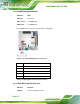


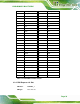
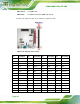
Table Of Contents
- 1 Introduction
- 2 Packing List
- 3 Connector Pinouts
- 3.1 Peripheral Interface Connectors
- 3.2 Internal Peripheral Connectors
- 3.2.1 ATX Power Signal Connector
- 3.2.2 Battery Connector
- 3.2.3 Digital I/O Connector
- 3.2.4 DisplayPort Connector
- 3.2.5 EC Debug Port
- 3.2.6 Fan Connector (CPU)
- 3.2.7 Fan Connector (System)
- 3.2.8 Front Panel Connector
- 3.2.9 Keyboard/Mouse Connector
- 3.2.10 LAN Active LED Connector
- 3.2.11 LVDS Connector
- 3.2.12 LVDS Backlight Connector
- 3.2.13 PCIe Mini Card Slot (Full-size)
- 3.2.14 PCIe Mini Card Slot (Half-size)
- 3.2.15 PCI Express x16 Slot
- 3.2.16 Power Button (On-board)
- 3.2.17 Power Connector (12V)
- 3.2.18 RS-232 Serial Port Connectors (COM2 ~ COM5)
- 3.2.19 RS-422/485 Serial Port Connector (COM6)
- 3.2.20 SATA 6Gb/s Drive Connectors
- 3.2.21 SATA 3Gb/s Drive Connectors
- 3.2.22 SATA Power Connectors
- 3.2.23 SMBus Connector
- 3.2.24 SO-DIMM Connectors
- 3.2.25 SPI Flash Connector
- 3.2.26 SPI Flash Connector (EC)
- 3.2.27 TPM Connector
- 3.2.28 USB 2.0 Connectors
- 3.2.29 USB 3.0/2.0 Connector
- 3.3 External Interface Connectors
- 4 Installation
- 4.1 Anti-static Precautions
- 4.2 Installation Considerations
- 4.3 Cooling Kit Installation
- 4.4 SO-DIMM Installation
- 4.5 PCIe Mini Card Installation
- 4.6 Jumper Settings
- 4.7 Chassis Installation
- 4.8 Internal Peripheral Device Connections
- 4.9 External Peripheral Interface Connection
- 4.10 Intel® AMT Setup Procedure
- 5 BIOS
- 5.1 Introduction
- 5.2 Main
- 5.3 Advanced
- 5.3.1 ACPI Settings
- 5.3.2 RTC Wake Settings
- 5.3.3 Trusted Computing
- 5.3.4 CPU Configuration
- 5.3.5 SATA Configuration
- 5.3.6 Intel(R) Rapid Start Technology
- 5.3.7 AMT Configuration
- 5.3.8 USB Configuration
- 5.3.9 iWDD H/W Monitor
- 5.3.10 F81866 Super IO Configuration
- 5.3.11 F81866 H/W Monitor
- 5.3.12 Serial Port Console Redirection
- 5.3.13 iEi Feature
- 5.4 Chipset
- 5.5 Boot
- 5.6 Security
- 5.7 Save & Exit
- 6 Software Drivers
- A BIOS Options
- B One Key Recovery
- C Terminology
- D Digital I/O Interface
- E Hazardous Materials Disclosure
KINO-DQM871 Mini-ITX SBC
Page 34
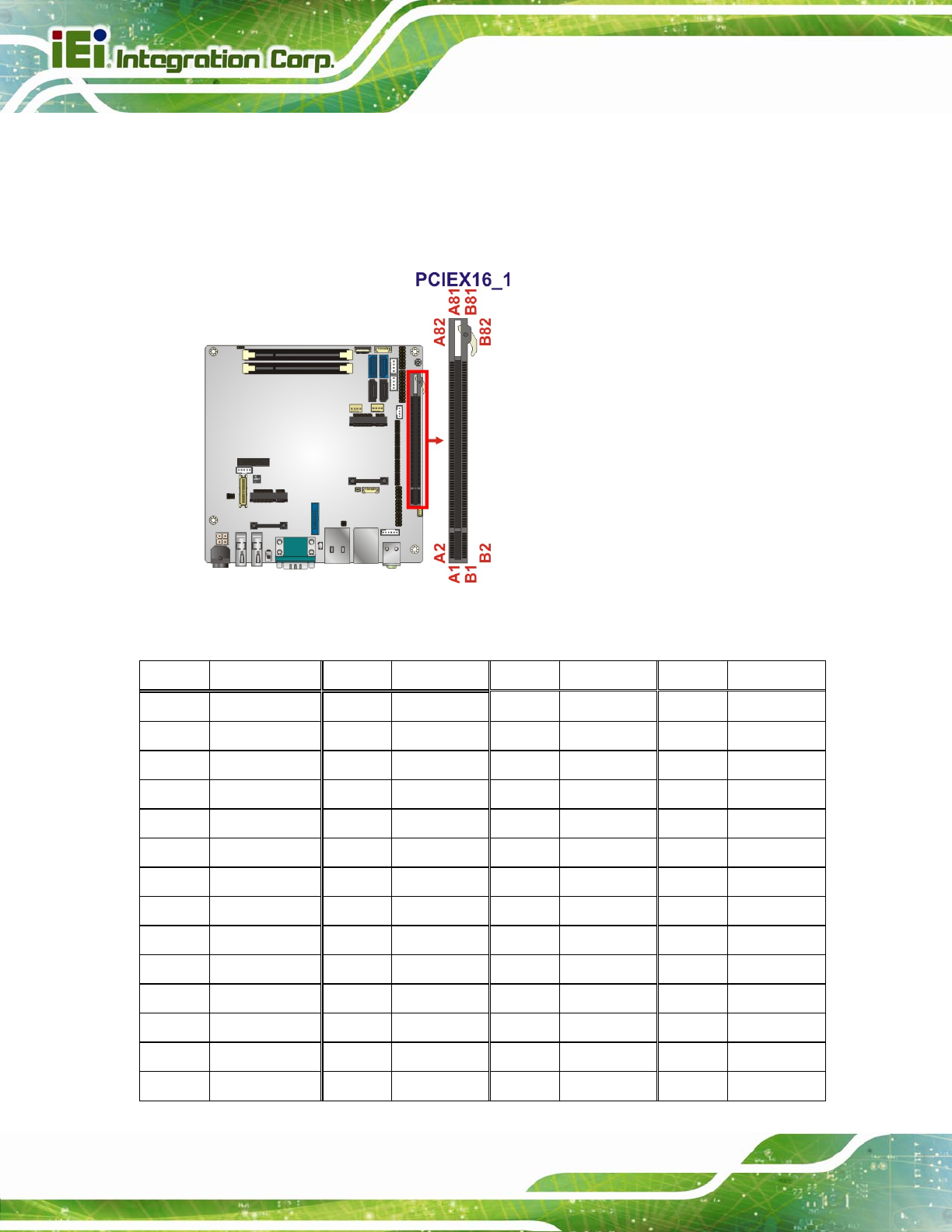
CN Location:
See
Figure 3-16
CN Pinouts:
See
Table 3-17 (Side A) Table 3-18 (Side B)
The PCIe x16 expansion cards slot is for PCIe x16 expansion cards.
Figure 3-16: PCIe x16 Slot Location
Pin Description Pin Description
Pin Description
Pin Description
A1 Name A22 HSIn(1) A43 HSIp(6) A64 HSIp(11)
A2 PRSNT#1 A23 GND A44 HSIn(6) A65 HSIn(11)
A3 +12v A24 GND A45 GND A66 GND
A4 +12v A25 HSIp(2) A46 GND A67 GND
A5 GND A26 HSIn(2) A47 HSIp(7) A68 HSIp(12)
A6 JTAG2 A27 GND A48 HSIn(7) A69 HSIn(12)
A7 JTAG3 A28 GND A49 GND A70 GND
A8 JTAG4 A29 HSIp(3) A50 RSVD A71 GND
A9 JTAG5 A30 HSIn(3) A51 GND A72 HSIp(13)
A10 +3.3v A31 GND A52 HSIp(8) A73 HSIn(13)
A11 +3.3v A32 RSVD A53 HSIn(8) A74 GND
A12 PWRGD A33 RSVD A54 GND A75 GND
A13 GND A34 GND A55 GND A76 HSIp(14)
A14 REFCLK+ A35 HSIp(4) A56 HSIp(9) A77 HSIn(14)