
Manual
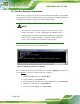
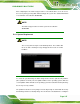
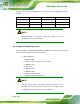


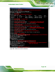
Table Of Contents
- 1 Introduction
- 2 Packing List
- 3 Connector Pinouts
- 3.1 Peripheral Interface Connectors
- 3.2 Internal Peripheral Connectors
- 3.2.1 ATX Power Signal Connector
- 3.2.2 Battery Connector
- 3.2.3 Digital I/O Connector
- 3.2.4 DisplayPort Connector
- 3.2.5 EC Debug Port
- 3.2.6 Fan Connector (CPU)
- 3.2.7 Fan Connector (System)
- 3.2.8 Front Panel Connector
- 3.2.9 Keyboard/Mouse Connector
- 3.2.10 LAN Active LED Connector
- 3.2.11 LVDS Connector
- 3.2.12 LVDS Backlight Connector
- 3.2.13 PCIe Mini Card Slot (Full-size)
- 3.2.14 PCIe Mini Card Slot (Half-size)
- 3.2.15 PCI Express x16 Slot
- 3.2.16 Power Button (On-board)
- 3.2.17 Power Connector (12V)
- 3.2.18 RS-232 Serial Port Connectors (COM2 ~ COM5)
- 3.2.19 RS-422/485 Serial Port Connector (COM6)
- 3.2.20 SATA 6Gb/s Drive Connectors
- 3.2.21 SATA 3Gb/s Drive Connectors
- 3.2.22 SATA Power Connectors
- 3.2.23 SMBus Connector
- 3.2.24 SO-DIMM Connectors
- 3.2.25 SPI Flash Connector
- 3.2.26 SPI Flash Connector (EC)
- 3.2.27 TPM Connector
- 3.2.28 USB 2.0 Connectors
- 3.2.29 USB 3.0/2.0 Connector
- 3.3 External Interface Connectors
- 4 Installation
- 4.1 Anti-static Precautions
- 4.2 Installation Considerations
- 4.3 Cooling Kit Installation
- 4.4 SO-DIMM Installation
- 4.5 PCIe Mini Card Installation
- 4.6 Jumper Settings
- 4.7 Chassis Installation
- 4.8 Internal Peripheral Device Connections
- 4.9 External Peripheral Interface Connection
- 4.10 Intel® AMT Setup Procedure
- 5 BIOS
- 5.1 Introduction
- 5.2 Main
- 5.3 Advanced
- 5.3.1 ACPI Settings
- 5.3.2 RTC Wake Settings
- 5.3.3 Trusted Computing
- 5.3.4 CPU Configuration
- 5.3.5 SATA Configuration
- 5.3.6 Intel(R) Rapid Start Technology
- 5.3.7 AMT Configuration
- 5.3.8 USB Configuration
- 5.3.9 iWDD H/W Monitor
- 5.3.10 F81866 Super IO Configuration
- 5.3.11 F81866 H/W Monitor
- 5.3.12 Serial Port Console Redirection
- 5.3.13 iEi Feature
- 5.4 Chipset
- 5.5 Boot
- 5.6 Security
- 5.7 Save & Exit
- 6 Software Drivers
- A BIOS Options
- B One Key Recovery
- C Terminology
- D Digital I/O Interface
- E Hazardous Materials Disclosure
KINO-DQM871 Mini-ITX SBC
Page 154
NOTE:
Use the following commands to check if the partitions were created
successfully.
Step 6: Press any key to exit the recovery tool and automatically reboot the system.
Please continue to the following procedure: Build the Recovery Partition.Step 0:
B.2.3 Install Operating System, Drivers and Applications
Install the operating system onto the unlabelled partition. The partition labeled "Recovery"
is for use by the system recovery tool and should not be used for installing the operating
system or any applications.
NOTE:
The operating system installation program may offer to reformat the
chosen partition. DO NOT format the partition again. The partition has
already been formatted and is ready for installing the new operating
system.
To install the operating system, insert the operating system installation CD into the optical
drive. Restart the computer and follow the installation instructions.