
Manual
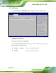
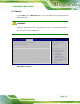


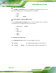


Table Of Contents
- 1 Introduction
- 2 Packing List
- 3 Connector Pinouts
- 3.1 Peripheral Interface Connectors
- 3.2 Internal Peripheral Connectors
- 3.2.1 ATX Power Signal Connector
- 3.2.2 Battery Connector
- 3.2.3 Digital I/O Connector
- 3.2.4 DisplayPort Connector
- 3.2.5 EC Debug Port
- 3.2.6 Fan Connector (CPU)
- 3.2.7 Fan Connector (System)
- 3.2.8 Front Panel Connector
- 3.2.9 Keyboard/Mouse Connector
- 3.2.10 LAN Active LED Connector
- 3.2.11 LVDS Connector
- 3.2.12 LVDS Backlight Connector
- 3.2.13 PCIe Mini Card Slot (Full-size)
- 3.2.14 PCIe Mini Card Slot (Half-size)
- 3.2.15 PCI Express x16 Slot
- 3.2.16 Power Button (On-board)
- 3.2.17 Power Connector (12V)
- 3.2.18 RS-232 Serial Port Connectors (COM2 ~ COM5)
- 3.2.19 RS-422/485 Serial Port Connector (COM6)
- 3.2.20 SATA 6Gb/s Drive Connectors
- 3.2.21 SATA 3Gb/s Drive Connectors
- 3.2.22 SATA Power Connectors
- 3.2.23 SMBus Connector
- 3.2.24 SO-DIMM Connectors
- 3.2.25 SPI Flash Connector
- 3.2.26 SPI Flash Connector (EC)
- 3.2.27 TPM Connector
- 3.2.28 USB 2.0 Connectors
- 3.2.29 USB 3.0/2.0 Connector
- 3.3 External Interface Connectors
- 4 Installation
- 4.1 Anti-static Precautions
- 4.2 Installation Considerations
- 4.3 Cooling Kit Installation
- 4.4 SO-DIMM Installation
- 4.5 PCIe Mini Card Installation
- 4.6 Jumper Settings
- 4.7 Chassis Installation
- 4.8 Internal Peripheral Device Connections
- 4.9 External Peripheral Interface Connection
- 4.10 Intel® AMT Setup Procedure
- 5 BIOS
- 5.1 Introduction
- 5.2 Main
- 5.3 Advanced
- 5.3.1 ACPI Settings
- 5.3.2 RTC Wake Settings
- 5.3.3 Trusted Computing
- 5.3.4 CPU Configuration
- 5.3.5 SATA Configuration
- 5.3.6 Intel(R) Rapid Start Technology
- 5.3.7 AMT Configuration
- 5.3.8 USB Configuration
- 5.3.9 iWDD H/W Monitor
- 5.3.10 F81866 Super IO Configuration
- 5.3.11 F81866 H/W Monitor
- 5.3.12 Serial Port Console Redirection
- 5.3.13 iEi Feature
- 5.4 Chipset
- 5.5 Boot
- 5.6 Security
- 5.7 Save & Exit
- 6 Software Drivers
- A BIOS Options
- B One Key Recovery
- C Terminology
- D Digital I/O Interface
- E Hazardous Materials Disclosure
KINO-DQM871 Mini-ITX SBC
Page 109
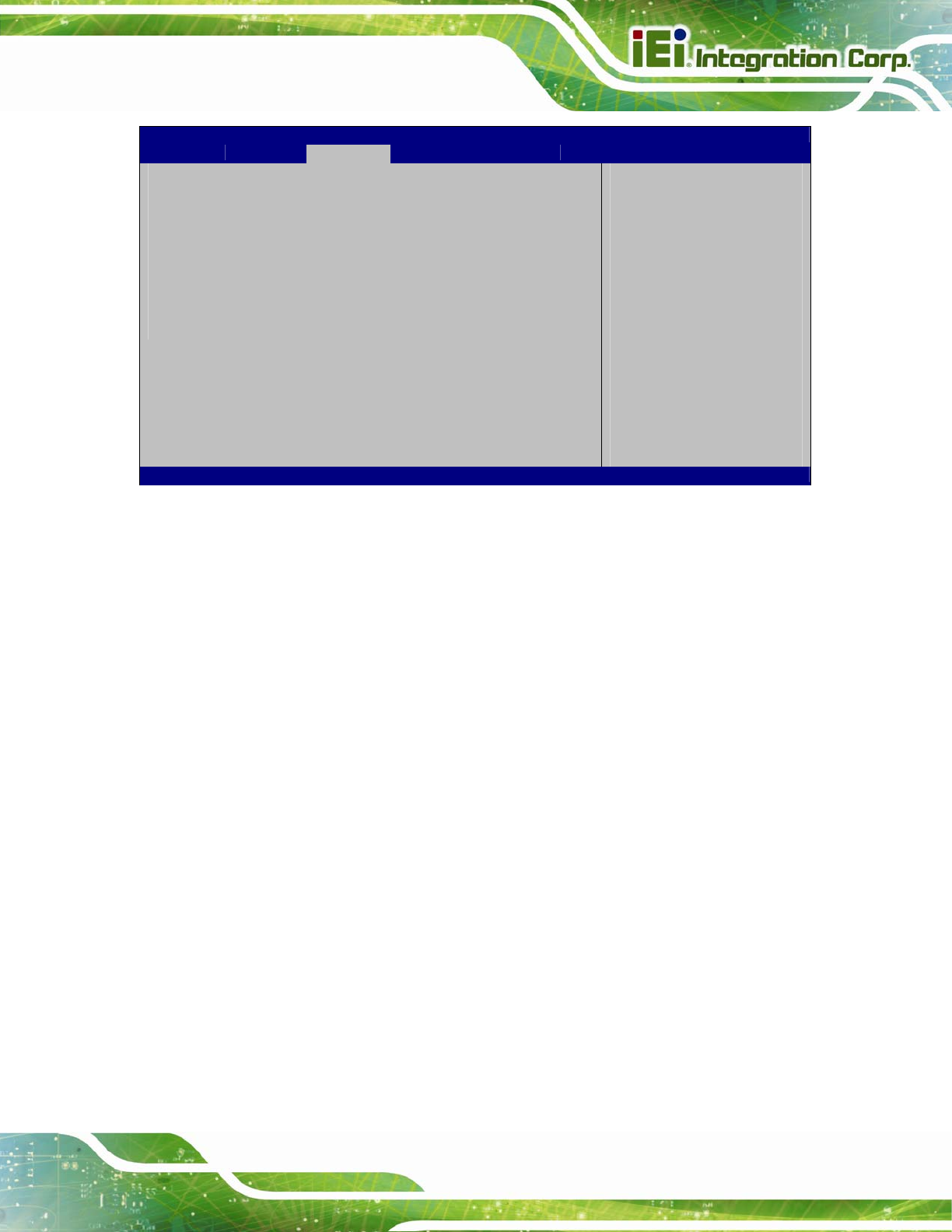
Aptio Setup Utility – Copyright (C) 2012 American Megatrends, Inc.
Chipset
Graphics Configuration
Primary Display [Auto]
DVMT Pre-Allocated [256M]
DVMT Total Gfx Mem [MAX]
Primary IGFX Boot Display [VBIOS Default]
Backlight Control [Inverted]
Select which of
IGFX/PEG/PCI Graphics
d
evice should be Primary
D
isplay Or select SG for
Switchable Gfx.
----------------------
: Select Screen
↑ ↓: Select Item
Enter: Select
+/-: Change Opt.
F1: General Help
F2: Previous Values
F3: Optimized Defaults
F4: Save & Exit
ESC: Exit
Version 2.15.1236. Copyright (C) 2012 American Megatrends, Inc.
BIOS Menu 21: Graphics Configuration
Primary Display [Auto]
Use the Primary Display option to select the primary graphics controller the system uses.
The following options are available:
Auto Default
IGFX
PEG
PCIE
DVMT Pre-Allocated [256M]
Use the DVMT Pre-Allocated option to set the amount of system memory allocated to the
integrated graphics processor when the system boots. The system memory allocated can
then only be used as graphics memory, and is no longer available to applications or the
operating system. Configuration options are listed below:
32M
64M
128M
256M Default
512M